24
The status of the four digital inputs is indicated using four circles, one for each digital input. If the circle
for a given digital input is grey, that indicates that the digital input is not receiving a signal from the
attached device (i.e. it is off). If the circle is green, that indicates that the digital input is receiving a signal
from the attached device (i.e. it is on). Digital inputs can be used to remotely initiate a specific stream
analysis. They must be configured via the AccuLase-GPA™ web GUI before they can be used.
This panel has no user-configurable parameters – it is used for display purposes only.
3.7 Outputs Panel
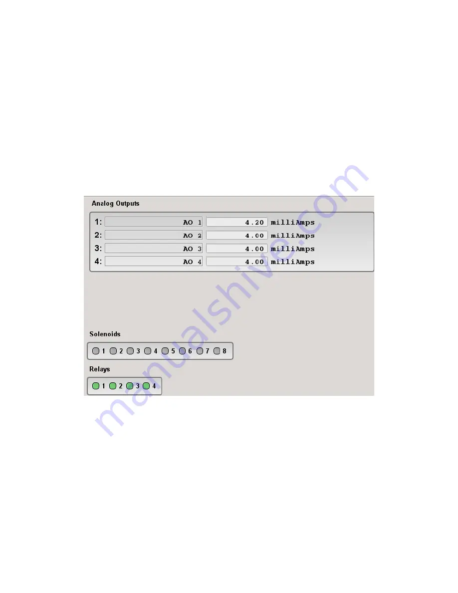
The Outputs panel shows the current status of the AccuLase-GPA™ IO board’s analog outputs (up to 4,
one per configured stream), solenoid outputs (8), and solid-state relays (4). It is shown in Figure 20.
Figure 12: Outputs Panel
For each analog output, the current signal being output from that output is displayed. Using a multimeter,
the current reading can be measured to compare against this value. If the current value measured by the
multimeter is not the same as the current value displayed on this panel, this indicates that the analog
output channel requires calibration. Calibration of the analog output channels can be done using the
AccuLase-GPA™ web GUI.
The status of the eight solenoid drivers and four relays are indicated using a circle for each solenoid and
relay. If the circle is grey, this indicates that the solenoid or relay is currently off. If the circle is green, that
indicates that the solenoid or relay is currently on.


