background image

4.2 Names and Functions of Parts

4.2.3

Rear side

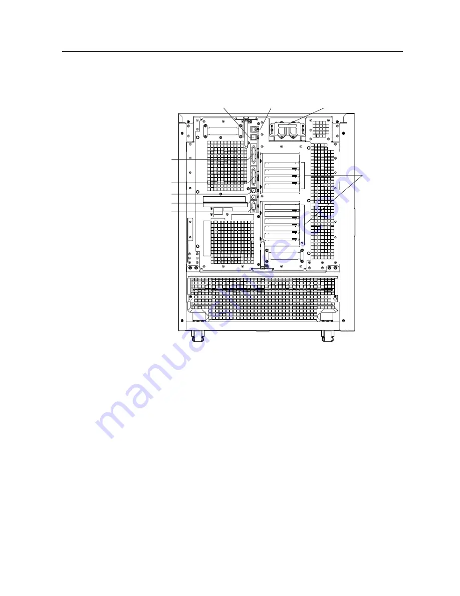
The names and functions of parts on the rear of the PRIMEPOWER400 Pedestal Server are as follows.

(1) AC power inputs

(2) PCI slots

(5) RCI port

(4) UPS port

(3) Power control port

(9) 100Base-TX port

(8) Keyboard port

(6) Serial port A

(7) Serial port B

Figure 4.4

Rear of PRIMEPOWER400 Pedestal Server

(1) AC power inputs

Connect the power cables to these points. Both AC power cords must be plugged into the same

power grid / circuit.

(2) PCI slots

PCI slots conform to the PCI local bus specifications (Rev. 2.1).

64-bit bus, 33MHz (5.0 V) and 33/66MHz (3.3V) are supported.

Both short cards (17.46 cm, 6.87 in.) and long cards (31.19 cm, 12.3 in.) are supported.

(3) Power control port (label : PC)

8-pin DIN for power control

(4) UPS port (label : UPS)

Dsub-9 pin for connecting the signal cable of an uninterruptible power supply

(5) RCI port (label : RCI)

RJ11 connector for connecting the RCI cable and terminator (provided with the server unit)

51

Summary of Contents for Primepower200

Page 1: ...P321 E122 04EN PRIMEPOWER PRIMEPOWER200 PRIMEPOWER400 PRIMEPOWER600 ...

Page 2: ......

Page 3: ...ventions Operating Environment Prohibited Uses FCC Class A Notice Trademarks Copyright SAFE OPERATION Using This Manual This manual contains important information regarding the use and handling of this product Read this manual thoroughly Pay special attention to the section Important Warnings Use the product according to the instructions and information available in this manual FUJITSU makes every...

Page 4: ... preparations for use and expansion CHAPTER 7 PRIMEPOWER600 Pedestal Server Chapter 7 gives an overview of the PRIMEPOWER600 Pedestal Server names and functions of parts preparations for use and expansion CHAPTER 8 PRIMEPOWER600 Rackmount 10U Server Chapter 8 gives an overview of the PRIMEPOWER600 Rackmount 10U Server names and functions of parts preparations for use and expansion CHAPTER 9 Expans...

Page 5: ...could result in minor or moderate personal injury if the user does not perform the procedure correctly It also indicates that damage to the product or other property may occur of the user does not perform the procedure correctly IMPORTANT This indicates information that could help the user use the product more efficiently How warning messages are displayed in the manual Each warning message is acc...

Page 6: ...th our sale person in charge before such use Documents produced by FUJITSU may contain technology controlled under the Foreign Exchange and Foreign Trade Control Law of Japan Those documents containing such technology should not be exported from Japan or transferred to anyone other than residents of Japan without first obtaining license from the Ministry of International Trade and Industry of Japa...

Page 7: ...cting its use copying distribution and recompilation No part of this product or related documentation may be reproduced in any form by any means without prior written authorization of Fujitsu Limited and its licensors if any The contents of this manual may be revised without prior notice All Rights Reserved Copyright c FUJITSU LIMITED 2001 v ...

Page 8: ...ocedure correctly Normal Operation Warnings task Electric shock fire Electric shock fire Do not deform damage or strip the power cable Doing so might cause electric shock or fire If you detect an abnormality such as heat build up smoke or foul odor immediately turn the main line switch OFF or disconnect the power cable and contact a service engineer Failure to do so might cause electric shock or f...

Page 9: ... Are floppy disks or tape cartridges still inserted in their drives If necessary back up files before turning the power off If improper commands are used at the ok prompt data may be lost If you need to use any other commands except those given in this manual you should fully understand the function and usage of the command before using it Except in any emergency never turn the AC main line switch...

Page 10: ...nection disconnection of external interface cables Maintenance repair and periodic diagnosis and maintenance CAUTION The following operations on this product and options provided by FUJITSU should be performed by a service engineer and should not be performed by the user Otherwise the user may cause the products to malfunction Unpacking of option adapter etc delivered to the customer Removal of th...

Page 11: ...Remodeling and Recycling of This Product If this product is remodeled with secondhand parts overhauled or recycled as is users and bystanders may be injured and property damaged unexpectedly ix ...

Page 12: ......

Page 13: ...e 5 2 2 2 Control panel 6 2 2 3 Rear side 8 2 3 Preparations for Use 10 2 3 1 Installation notes 10 2 3 2 Installation specifications 12 2 3 3 Connecting the console 14 2 3 4 Turning the power on 14 2 3 5 Turning the power off 16 2 3 6 Installing the Enhanced Support Facility package 17 2 3 7 How to enable disable the break signal 18 2 3 8 LAN expansion note 19 i ...

Page 14: ...30 3 3 Preparations for Use 31 3 3 1 Installation notes 31 3 3 2 Installation specifications 33 3 3 3 Connecting the console 34 3 3 4 Turning the power on 35 3 3 5 Turning the power off 37 3 3 6 Installing the Enhanced Support Facility package 38 3 3 7 How to enable disable the break signal 39 3 3 8 LAN expansion note 40 3 4 Expanding the Server Unit 41 3 4 1 Adding power supply units 42 3 4 2 Add...

Page 15: ... 55 4 3 5 Turning the power off 57 4 3 6 Installing the Enhanced Support Facility package 58 4 3 7 How to enable disable the break signal 59 4 3 8 LAN expansion note 60 4 4 Expanding the Server Unit 61 4 4 1 Adding power supply units 62 4 4 2 Adding CPU modules 63 4 4 3 Adding memory modules 63 4 4 4 Adding hard disk drives 64 4 4 5 Adding PCI cards 65 CHAPTER 5 PRIMEPOWER400 Rackmount 4U Server 6...

Page 16: ...ding the Server Unit 82 5 4 1 Adding power supply units 84 5 4 2 Adding CPU modules 85 5 4 3 Adding memory modules 86 5 4 4 Adding hard disk drives 86 5 4 5 Adding PCI cards 87 CHAPTER 6 PRIMEPOWER400 Rackmount 10U Server 89 6 1 Overview 90 6 2 Names and Functions of Parts 91 6 2 1 Front side 91 6 2 2 Control panel 92 6 2 3 Rear side 94 6 3 Preparations for Use 96 6 3 1 Installation notes 96 6 3 2...

Page 17: ...destal Server 115 7 1 Overview 116 7 2 Names and Functions of Parts 117 7 2 1 Front side 117 7 2 2 Control panel 118 7 2 3 Rear side 121 7 3 Preparations for Use 122 7 3 1 Installation notes 122 7 3 2 Installation specifications 124 7 3 3 Connecting the console 126 7 3 4 Turning the power on 126 7 3 5 Turning the power off 128 7 3 6 Installing the Enhanced Support Facility package 129 7 3 7 How to...

Page 18: ... 8 3 2 Installation specifications 148 8 3 3 Connecting the console 149 8 3 4 Turning the power on 150 8 3 5 Turning the power off 151 8 3 6 Installing the Enhanced Support Facility package 152 8 3 7 How to enable disable the break signal 153 8 3 8 LAN expansion note 154 8 4 Expanding the Server Unit 155 8 4 1 Adding power supply units 158 8 4 2 Adding CPU modules 158 8 4 3 Adding memory modules 1...

Page 19: ...k drives 176 CHAPTER 10 Expansion File Unit Type 2 177 10 1 Overview 178 10 2 Names and Functions of Parts 178 10 2 1 Front side 178 10 2 2 Rear side 179 10 3 Preparations for Use 180 10 3 1 Installation notes 180 10 3 2 Installation specifications 182 10 4 Disk Drive Configurations 182 10 5 Hot swapping Redundant Components 183 10 5 1 Power supply units 183 10 5 2 Hard disk drives 184 CHAPTER 11 ...

Page 20: ...S settings 193 11 3 4 Data cartridges 194 11 3 5 Data cartridge handling precautions 195 11 3 6 Write protecting a data cartridge 196 11 3 7 Loading a data cartridge 196 11 3 8 Ejecting a data cartridge 196 11 3 9 Cleaning the tape heads 197 11 4 DAT Drive DDS4 198 11 4 1 Names and functions of parts 198 11 4 2 SCSI ID 199 11 4 3 OS settings 200 11 4 3 1 PRIMEPOWER200 Non Pedestal Servers 200 11 4...

Page 21: ...data cartridge 211 11 5 8 Ejecting a data cartridge 212 11 5 9 Cleaning the tape heads 212 11 6 DLT Tape Drive 215 11 6 1 Names and functions of parts 215 11 6 2 SCSI ID 217 11 6 3 OS settings 218 11 6 4 Data cartridge 219 11 6 5 Data cartridge handling precautions 220 11 6 6 Write protecting a data cartridge 221 11 6 7 Loading a data cartridge 221 11 6 8 Ejecting a data cartridge 222 11 6 9 Clean...

Page 22: ...3 1 Overview 232 13 2 Checking Errors from the ok Prompt 232 13 3 LCD Initial Diagnostics Sequence 233 13 4 SCF Error Messages 234 13 5 Post Error Messages 237 CHAPTER 14 Glossary 239 14 1 Glossary 240 x ...

Page 23: ...ion of PCI slots 24 Figure 3 1 PRIMEPOWER200 Rackmount 4U Server 26 Figure 3 2 Front of PRIMEPOWER200 Rackmount 4U Server 27 Figure 3 3 Control Panel 27 Figure 3 4 Rear of PRIMEPOWER200 Rackmount 4U Server 30 Figure 3 5 Turning the power on 36 Figure 3 6 Turning the power off 38 Figure 3 7 PRIMEPOWER200 Rackmount 4U Systemboard 41 Figure 3 8 Rear View of PRIMEPOWER200 Rackmount 4U showing position...

Page 24: ...er 94 Figure 6 5 Turning the power on 102 Figure 6 6 Turning the power off 104 Figure 6 7 PRIMEPOWER400 Rackmount 10U Systemboard 108 Figure 6 8 PRIMEPOWER400 Rackmount 10U PCI boards 109 Figure 6 9 Rear of PRIMEPOWER400 Rackmount 10U showing position of PCI slots 113 Figure 7 1 PRIMEPOWER600 Pedestal Server 116 Figure 7 2 Front of PRIMEPOWER600 Pedestal Server 117 Figure 7 3 Control Panel 118 Fig...

Page 25: ...rive Configuration of Expansion File Unit Type 2 183 Figure 10 4 Disk Drive Tape Drive Configuration of Expansion File Unit Type 2 183 Figure 11 1 Front Panel CD ROM Drive 188 Figure 11 2 CD ROM Disc Mark 189 Figure 11 3 Front Panel of DDS3 DAT Drive 191 Figure 11 4 DAT Data Cartridge Write protection Tab 196 Figure 11 5 Front Panel of DDS4 DAT Drive 198 Figure 11 6 DAT Data Cartridge Write protec...

Page 26: ...POWER200 Rackmount 4U Server 2 2 34 Table 3 4 Allowed CPU Module Configurations 42 Table 3 5 PCI Slot Specifications 44 Table 4 1 MODE Switch Settings 49 Table 4 2 Installation Specifications of the PRIMEPOWER400 Pedestal Server 1 2 53 Table 4 3 Installation Specifications of the PRIMEPOWER400 Pedestal Server 2 2 54 Table 4 4 Allowed CPU Module Configurations 63 Table 4 5 PCI Slot Specifications 6...

Page 27: ...2 2 149 Table 8 4 Allowed CPU Module Configurations 159 Table 8 5 PCI Slot Specifications 162 Table 9 1 CHECK LED Indicator 168 Table 9 2 Installation Specifications of the Expansion Disk Cabinet 1 2 172 Table 9 3 Installation Specifications of the Expansion Disk Cabinet 2 2 173 Table 10 1 CHECK LED 179 Table 10 2 Installation Specification of Expansion File Unit Type 2 182 Table 11 1 DDS3 DAT Dri...

Page 28: ...r Messages 234 Table 13 3 Power Supply Unit Fans and Environmental Error Messages 235 Table 13 4 CPU Monitor Error Massages 235 Table 13 5 Lithium Battery Error Messages 236 Table 13 6 Other Error Massages 236 Table 13 7 Post Error Messages 237 xvi ...

Page 29: ...igh performance Multi Processor Platform Symmetric Multiprocessing SMP architecture maximum number of CPUs varies from model to model Memory interleaving maximum number of interleaves varies from model to model Implements a packet based bus protocol with a throughput of 1 3 to 1 6 GB s per processor A high speed crossbar switched multiprocessor interface is used This enables simultaneous operation...

Page 30: ...LAN Parity IP checksum Note ECC or parity does not protect the RS 232C serial interface and floppy disk Power on diagnostics are conducted on system components such as processors and memory Automatic System Reconfiguration ASR isolates faulty hardware components such as processors and memory modules immediately after detection A SCF System Control Facility which has an integrated service processor...

Page 31: ...n overview of the PRIMEPOWER200 Pedestal Server names and functions of parts preparations for use and how to expand the server unit CONTENTS 2 1 Overview 4 2 2 Names and Functions of Parts 5 2 3 Preparations for Use 10 2 4 Expanding the Server Unit 20 3 ...

Page 32: ... slots 2 x 33 66MHz 4 x 33MHz are provided Up to eight UltraSCSI disk drives can be built in One tape unit DDS4 DAT 8mm can be installed A CD ROM drive is provided as standard One 100Base TX port two serial ports RS 232C and one keyboard mouse port are provided as standard Appearance The following illustration shows the appearance of the PRIMEPOWER200 Pedestal Server CHECK LED Amber POWER LED Gree...

Page 33: ...POWER200 Pedestal Server 1 Control panel Contains various switches and indicator LEDs See 2 2 2 Control Panel for details 2 Panel cover The panel cover can be opened to its right after being unlocked The LCD panel and the POWER and CHECK LEDs can be checked with the cover closed 3 Stabilizing feet The stabilizing feet prevent the PRIMEPOWER200 Pedestal Server from falling over when pushed from the...

Page 34: ...ta Destruction Install the Enhanced Support Facility before using the system Without this package a front panel miss operation or hardware error may cause the system to shutdown or data to be lost The MODE switch has three settings and is used to specify the run mode at power on or system reboot and to whether the POWER RESET and REQUEST switches are enabled or disabled Table 2 1 MODE Switch Setti...

Page 35: ... on and off Power on and off of expansion units such as the Expansion Disk Cabinet is interlocked with the powering on and off of the PRIMEPOWER200 Pedestal Server Operation of the POWER switch varies according to the MODE switch and scftool software contained in the Enhanced Support Facility settings For details see 2 MODE switch and the Enhanced Support Facility User s Guide 6 CHECK LED IMPORTAN...

Page 36: ...f parts on the rear of the PRIMEPOWER200 Pedestal Server are as follows AC main line switch 1 AC power input 2 PCI slots 3 RCI port 6 UPS port 5 Power control port 4 100Base TX port 10 Keyboard port 9 Serial port A 7 Serial port B 8 Figure 2 4 Rear of PRIMEPOWER200 Pedestal Server 8 ...

Page 37: ... cards 31 19 cm 12 3 in are supported 4 Power control port label PC 8 pin DIN for power control 5 UPS port label UPS Dsub 9 pin for connecting the signal cable of an uninterruptible power supply 6 RCI port label RCI RJ11 connector for connecting the RCI cable and terminator provided with server unit 7 8 Serial ports label SERIAL A B Dsub 25 pin ports for connecting a console terminal when performi...

Page 38: ...power supply source is grounded properly using a maximum resistance of 100 Ohms Also do not ground the AC power supply source using a shared ground Use only an independent grounding point Otherwise the PRIMEPOWER200 Pedestal Server may malfunction Do not run a cable under a unit or allow a cable to become taut Do not disconnect the power cable when the power is on Do not place anything on the PRIM...

Page 39: ...ines If all of the power cables are connected to a single power strip high leakage current exceeding the stipulated value may leak through to the earth lead of the power strip If the power strip is not directly connected to the main distribution panel use a power strip with an industrial plug 11 ...

Page 40: ...perating 20 80 RH non condensing Non operating 8 80 RH non condensing Vibration Operating 0 2 G Non operating 0 4 G Noise 47 db A 2 Form Factor Pedestal 2 5 A 240V Single phase AC100 120V 10 Single phase AC200 240V 10 3 5 mA 100Ω 5 35 ûC 41 95 F 1 0 50 ûC 32 122 F 1 If the ambient temperature exceeds 35 deg C 95 deg F during operation a warning message is displayed Take steps to rectify the proble...

Page 41: ...6 in 1 Including the Stabilizing Feet the width is 478 mm 19 inch and the depth is 657mm 26 inch 2 If it is possible to move the Server Unit so that 800 mm 32 inch or more space is available behind the unit when maintenance is performed then 200mm 8 inch of space is adequate is normal use However if optical cables are used at least 300mm 12 inch of space will be needed between the rear of the Unit...

Page 42: ...s operation according to the break signal For this reason data is sometimes lost IMPORTANT If the MODE switch is set to AUTO or SECURE on a server unit on which auto power control by software is set and the AC power is interrupted by operating the main line switch etc the power will sometimes automatically turn on at the moment that the AC power supply is resumed To keep the power from being turne...

Page 43: ...ices on Figure 2 5 Turning the power on 3 Press the POWER switch on the control panel of the PRIMEPOWER200 Pedestal Server The POWER LEDs of the PRIMEPOWER Server and any peripheral devices connected via the RCI port should now light up Note Operation of the POWER switch is disabled when the MODE switch is set to SECURE A keyboard power on function is not supported 15 ...

Page 44: ...pt during Solaris operation potentially causing data to be lost IMPORTANT If the MODE switch is set to AUTO or SECURE on a server unit on which auto power control by software is set and the AC power is interrupted by operating the main line switch etc the power will sometimes automatically turn on at the moment that the AC power supply is resumed To keep the power from being turned on automaticall...

Page 45: ...tion Install the Enhanced Support Facility before using the system Without this package a front panel miss operation or hardware error may cause the system to shutdown or data to be lost With the PRIMEPOWER servers be sure to install all of the programs provided with the Enhanced Support Facility to ensure the high reliability functions of the service processor For details refer to the User s Guid...

Page 46: ...rd To prevent this kind of response to a break signal arriving from the serial port or the STOP A command from the keyboard make the following settings using the set fw options command shown below from the ok prompt and then set the MODE switch on the control panel to the SECURE mode How to disable the break signal and STOP A command 1 Use the print fw options command to check the current setting ...

Page 47: ...ok print fw options fw options no break 2 Use the clear fw options command to cancel the no break setting ok clear fw options no break fw options 3 Use the print fw options command to make sure that nothing is set ok print fw options fw options 2 3 8 LAN expansion note When LAN ports have seen added with PCI cards and each LAN port given its own MAC address these should be enabled from the ok prom...

Page 48: ...lowing optional items can be added to the PRIMEPOWER200 Pedestal Server CPU modules Memory modules Hard disk drives PCI cards Systemboard mounting locations are as follows PC LAN KB Serial A Serial B 14 DDC 3 PCI Slot 6 CPU Slot 1 15 12 13 10 11 08 09 06 07 04 05 02 03 00 01 DDC 2 DDC 1 DDC 0 CPU Slot 0 SCF Board Only PCI Slot 5 PCI Slot 4 PCI Slot 3 PCI Slot 2 PCI Slot 1 NVRAM Memory Module Slots...

Page 49: ...TANT Operation for configurations other than those shown in Table 2 4 cannot be guaranteed Table 2 4 Allowed CPU Module Configurations O 0 1 DDC 0 DDC 1 1 O O DDC 2 DDC 3 2 CPU slot No of CPUs DDCs to be added incremental 2 4 No of DDCs 2 4 2 Adding memory modules A total of 16 memory module slots are provided on the PRIMEPOWER200 Pedestal Server Systemboard When adding memory modules the followin...

Page 50: ...0 to 3 is connected to the base UltraSCSI bus and the optional Disk Expansion Unit bays 0 to 3 should be connected to an UltraSCSI bus card installed in a PCI slot 0 1 2 3 0 1 2 3 Base SCSI Unit POWER LED Disk Expansion Unit ACTIVE LED Green FAULT LED Amber Figure 2 8 PRIMEPOWER200 Disk Drive Configuration CAUTION Data Destruction Set the UltraSCSI and PCI card buses correctly If these buses are s...

Page 51: ...rd connected to SCSI connector 1 of the UltraSCSI card in PCI slot 6 ok setenv led control 1 pci 17 4000 scsi 5 Hot swapping hard disk drives CAUTION Data Destruction Data may be lost if hot swapping of hard disk drives is not performed correctly Contact the service engineer if a hard disk drive must be hot swapped IMPORTANT To utilize the hot swapping functions of the hard disk drive use the opti...

Page 52: ...low for details of the PCI slot positions when installing PCI cards Table 2 5 PCI Slot Specifications PCI Bus Slot Card Width bits PCI Slot number PCI Clock Rate MHz Card Input Voltage 5V or Universal long short 6 5 4 3 2 1 D D D C B A 64 32 64 64 32 64 64 32 64 64 32 64 64 32 64 64 32 64 33 33 33 33 33 66 33 66 5V or Universal 5V or Universal 5V or Universal 3 3V or Universal 3 3V or Universal lo...

Page 53: ... overview of the PRIMEPOWER200 Rackmount 4U Server names and functions of parts preparations for use and how to expand the server unit CONTENTS 3 1 Overview 26 3 2 Names and Functions of Parts 27 3 3 Preparations for Use 31 3 4 Expanding the Server Unit 41 25 ...

Page 54: ...MHz are provided Up to two UltraSCSI disk drives can be built in One tape unit DDS4 DAT 8mm can be installed A CD ROM drive is provided as standard One 100Base TX port two serial ports RS 232C and one keyboard mouse port are provided as standard Redundant fan and N 1 redundant power supply configurations are supported Appearance The following illustration shows the appearance of the PRIMEPOWER200 ...

Page 55: ... 3 2 Front of PRIMEPOWER200 Rackmount 4U Server 1 Control panel Contains various switches and indicator LEDs See 3 2 2 Control Panel for details 3 2 2 Control panel The PRIMEPOWER200 Rackmount 4U Server is provided with the control panel shown in Figure 3 3 REQUEST RESET AUTO MANUAL 3 REQUEST Switch SECURE CHECK POWER 1 RESET Switch 2 MODE Switch 6 CHECK LED Amber 7 POWER LED Green 5 POWER Switch ...

Page 56: ...tch RESET switch REQUEST switch Operation mode MANUAL AUTO SECURE Enabled Enabled Enabled Enabled Disabled Disabled Disabled Disabled Disabled The OS is automatically booted after initial diagnostics are completed The TTY terminal break and keyboard STOP A commands are disabled while Solaris is operating The OS is automatically booted after initial diagnostics are completed The bootup sequence sto...

Page 57: ...g to the MODE switch and scftool software contained in the Enhanced Support Facility settings For details see 2 MODE switch and the Enhanced Support Facility User s Guide 6 CHECK LED IMPORTANT When the PRIMEPOWER200 Rackmount 4U Server detects an error in the power line or abnormal temperatures the CHECK LED blinks and the power is automatically turned off to prevent unit damage and ensure safety ...

Page 58: ... 0 V and 33 66MHz 3 3V are supported Both short cards 17 46 cm 6 87 in and long cards 31 19 cm 12 3 in are supported 3 RCI port label RCI RJ11 connector for connecting the RCI cable and terminator provided with server unit 4 UPS port label UPS Dsub 9 pin for connecting the signal cable of an uninterruptible power supply 5 Power control port label PC 8 pin DIN for power control 6 100Base TX port la...

Page 59: ...nsideration should be given to installing the PRIMEPOWER200 Rackmount 4U Server in an environment compatible with the manufacturer s maximum rated ambient temperature Consideration for adjustment of air conditions like air circulation should be given to prevent the internal rack ambient temperature from exceeding the maximum operating temperature of this unit Maximum internal operating temperature...

Page 60: ...n panel use a power strip with an industrial plug General installation notes Do not block the ventilation holes Do not install the PRIMEPOWER200 Rackmount 4U Server where it will be exposed to sunlight or sources of heat Do not install the PRIMEPOWER200 Rackmount 4U Server in dusty places or places where it will be exposed to corrosive gases or sea breezes Keep the PRIMEPOWER200 Rackmount 4U Serve...

Page 61: ...ent 6 1 A 100V Leak Current Frame Resistance Temperature Operating Non Operating Humidity Operating 20 80 RH non condensing Non Operating 8 80 RH non condensing Vibration Operating 0 2 G Non Operating 0 4 G Noise 50 db A 3 Form Factor Rackmount 4U 2 6 A 240V Single phase AC100 120V 10 Single phase AC200 240V 10 3 5 mA 100Ω 5 35 ûC 41 95 F 2 0 50 ûC 32 122 F 1 Include Rack Rail weight 2 If the ambi...

Page 62: ...e pull out area clear so that devices inside the PRIMEPOWER200 Rackmount 4U Server can be pulled out from the rack cabinet when performing maintenance 3 When a GP7B7RK3x RK4x rack cabinet is used 3 3 3 Connecting the console A device such as a personal computer must be connected to the serial port to act as the console for a PRIMEPOWER200 Rackmount 4U Server to which a display or keyboard is not c...

Page 63: ...the moment that the AC power supply is resumed To keep the power from being turned on automatically like this set the MODE switch to MANUAL when restoring AC power after an interruption When the PRIMEPOWER Server is turned on a self diagnostics routine automatically verifies whether or not hardware errors are occurring If this routine detects any hardware errors system power is automatically turne...

Page 64: ...the control panel of the PRIMEPOWER200 Rackmount 4U Server The POWER LEDs of the PRIMEPOWER Server and any peripheral devices connected via the RCI port should now light up Note Operation of the POWER switch is disabled when the MODE switch is set to SECURE A keyboard power on function is not supported 36 ...

Page 65: ...e ok prompt during Solaris operation potentially causing data to be lost IMPORTANT If the MODE switch is set to AUTO or SECURE on a server unit on which auto power control by software is set and the AC power is interrupted the power will sometimes automatically turn on at the moment that the AC power supply is resumed To keep the power from being turned on automatically like this set the MODE swit...

Page 66: ...ata Destruction Install the Enhanced Support Facility before using the system Without this package a front panel miss operation or hardware error may cause the system to shutdown or data to be lost With the PRIMEPOWER servers be sure to install each of the programs provided with the Enhanced Support Facility to ensure the high reliability functions of the service processor For details refer to the...

Page 67: ...nt this kind of response to a break signal arriving from the serial port or the STOP A command from the keyboard make the following settings using the set fw options command shown below from the ok prompt and then set the MODE switch on the control panel to the SECURE mode How to disable the break signal and STOP A command 1 Use the print fw options command to check the current setting values The ...

Page 68: ... enabled ok print fw options fw options no break 2 Use the clear fw options command to cancel the no break setting ok clear fw options no break fw options 3 Use the print fw options command to make sure that nothing is set ok print fw options fw options 3 3 8 LAN expansion note When LAN ports have seen added with PCI cards and each LAN port given its own MAC address these should be enabled from th...

Page 69: ...ms can be added to the PRIMEPOWER200 Rackmount 4U Server Power supply units CPU modules Memory modules Hard disk drives PCI cards Systemboard mounting locations are as follows PC UPS KB RCI LAN Serial A Serial B DDC 3 DDC 2 DDC 1 DDC 0 SCF Board Only NVRAM PCI Slot 1 PCI Slot 2 PCI Slot 3 PCI Slot 4 PCI Slot 5 PCI Slot 6 CPU Slot 0 CPU Slot 1 00 01 02 03 04 05 06 07 08 09 10 11 12 13 14 15 Memory ...

Page 70: ... on how to swap power supply units refer to the Machine Administration Instructions included with the Enhanced Support Facility 3 4 2 Adding CPU modules A total of two CPU module slots are provided on the PRIMEPOWER200 Rackmount 4U Systemboard When adding CPU modules the following restrictions apply Only SPARC64 GP processors can be used To ensure they all operate at the same clock speed have the ...

Page 71: ...reen when a hard disk drive is operating reading or writing The FAULT LED lights up according to the swapping procedure when hot swapping a hard disk drive Hot swapping hard disk drives CAUTION Data Destruction Data may be lost if hot swapping of hard disk drives is not performed correctly Contact the service engineer if a hard disk drive must be hot swapped IMPORTANT To utilize the hot swapping f...

Page 72: ...ow for details of the PCI slot positions when installing PCI cards Table 3 5 PCI Slot Specifications PCI Bus Slot Card Width bits PCI Slot number PCI Clock Rate MHz Card Input Voltage 5V or Universal long short 6 5 4 3 2 1 D D D C B A 64 32 64 64 32 64 64 32 64 64 32 64 64 32 64 64 32 64 33 33 33 33 33 66 33 66 5V or Universal 5V or Universal 5V or Universal 3 3V or Universal 3 3V or Universal lon...

Page 73: ... overview of the PRIMEPOWER400 Pedestal Server names and functions of parts preparations for use and how to expand the server unit CONTENTS 4 1 Overview 46 4 2 Names and Functions of Parts 47 4 3 Preparations for Use 52 4 4 Expanding the Server Unit 61 45 ...

Page 74: ... are provided Up to six UltraSCSI disk drives can be built in One tape unit DDS4 DAT 8mm or DLT can be installed A CD ROM drive is provided as standard One 100Base TX port two serial ports RS 232C and one keyboard mouse port are provided as standard Redundant fan and N 1 redundant power supply configurations are supported Appearance The following illustrations show the appearance of the PRIMEPOWER...

Page 75: ...ER400 Pedestal Server are as follows CD ROM Unit 1 Control Panel Floppy Disk Unit maintenance only 2 Front Panel open 8mm Tape Unit or DAT DDS4 Unit or DLT Unit option Figure 4 2 Front of PRIMEPOWER400 Pedestal Server 1 Control panel Contains various switches and indicator LEDs See 4 2 2 Control Panel for details 2 Front cover The panel cover can be opened to its right after being unlocked The LCD...

Page 76: ...SET switch push button CAUTION Data Destruction Pressing the RESET switch while the system is running may cause data to be lost The RESET switch is used to reset the system to its initial state and is enabled or disabled by the MODE switch described in 2 MODE switch 2 MODE switch 3 position slider CAUTION Data Destruction Install the Enhanced Support Facility before using the system Without this p...

Page 77: ...r has occurred in the system Only service engineers should operate the REQUEST switch 4 LCD panel The 16 digit x 2 row LCD panel displays the status of initial diagnostics performed when the power is turned on It also displays error messages when a hardware error has been detected For details on error messages that maybe displayed see 13 Troubleshooting A LCD panel error message is cleared by one ...

Page 78: ...lights up when the PRIMEPOWER400 Pedestal Server detects an error When the power is turned on the CHECK LED lights up and then goes out This is not an error If the CHECK LED stays lit and does not go out at power on this indicates an error When an error occurs note down the details displayed on the LCD panel and contact a service engineer 7 POWER LED The POWER LED indicates the power state of the ...

Page 79: ... cables to these points Both AC power cords must be plugged into the same power grid circuit 2 PCI slots PCI slots conform to the PCI local bus specifications Rev 2 1 64 bit bus 33MHz 5 0 V and 33 66MHz 3 3V are supported Both short cards 17 46 cm 6 87 in and long cards 31 19 cm 12 3 in are supported 3 Power control port label PC 8 pin DIN for power control 4 UPS port label UPS Dsub 9 pin for conn...

Page 80: ...Server may be damaged Be sure to follow these notes Do not block the ventilation holes Do not install the PRIMEPOWER400 Pedestal Server where it will be exposed to sunlight or sources of heat Do not install the PRIMEPOWER400 Pedestal Server in dusty places or places where it will be exposed to corrosive gases or sea breezes Keep the PRIMEPOWER400 Pedestal Server isolated from vibration Install the...

Page 81: ...r the PRIMEPOWER400 Pedestal Server Table 4 2 Installation Specifications of the PRIMEPOWER400 Pedestal Server 1 2 Item Specification Weight 125 kg 275 94 lb max Power Supply Voltage Frequency 50 60 Hz 2 4 Max Current 12 0 A Leak Current Frame Resistance Temperature Operating Non operating Humidity Operating 20 80 RH non condensing Non operating 8 80 RH non condensing Vibration Operating 0 2 G Non...

Page 82: ... 650 H 26 in 1000 2 39 in 580 23 in 1 Not including any projections 2 If it is possible to move the Server Unit so that 800 mm 32 inch or more space is available behind the unit when maintenance is performed then 200mm 8 inch of space is adequate is normal use However if optical cables are used at least 300mm 12 inch of space will be needed between the rear of the Unit and the wall 3 If it is poss...

Page 83: ...t to display of the ok prompt during Solaris operation potentially causing data to be lost IMPORTANT If the MODE switch is set to AUTO or SECURE on a server unit on which auto power control by software is set and the AC power is interrupted the power will sometimes automatically turn on at the moment that the AC power supply is resumed To keep the power from being turned on automatically like this...

Page 84: ...igure 4 5 Turning the power on 3 Press the POWER switch on the control panel of the PRIMEPOWER400 Pedestal Server The POWER LEDs of the PRIMEPOWER Server and any peripheral devices connected via the RCI port should now light up Note Operation of the POWER switch is disabled when the MODE switch is set to SECURE A keyboard power on function is not supported 56 ...

Page 85: ...the ok prompt during Solaris operation potentially causing data to be lost IMPORTANT If the MODE switch is set to AUTO or SECURE on a server unit on which auto power control by software is set and the AC power is interrupted the power will sometimes automatically turn on at the moment that the AC power supply is resumed To keep the power from being turned on automatically like this set the MODE sw...

Page 86: ...Destruction Install the Enhanced Support Facility before using the system Without this package a front panel miss operation or hardware error may cause the system to shutdown or data to be lost With the PRIMEPOWER servers be sure to install all of the programs provided with the Enhanced Support Facility to ensure the high reliability functions or the service processor For details refer to the User...

Page 87: ...s kind of response to a break signal arriving from the serial port or the STOP A command from the keyboard make the following settings using the set fw options command shown below with the ok prompt displayed on screen and then set the MODE switch on the control panel to the SECURE mode How to disable the break signal and STOP A command 1 Use the print fw options command to check the current setti...

Page 88: ...nabled ok print fw options fw options no break 2 Use the clear fw options command to cancel the no break setting ok clear fw options no break fw options 3 Use the print fw options command to make sure that nothing is set ok print fw options fw options 4 3 8 LAN expansion note When LAN ports have seen added with PCI cards and each LAN port given its own MAC address these should be enabled from the ...

Page 89: ...r supply units CPU modules Memory modules Hard disk drives PCI cards Systemboard mounting locations are as follows DDC 7 DDC 6 DDC 5 DDC 4 CPU slot 2 CPU slot 3 Memory slot 00 Memory slot 02 Memory slot 04 Memory slot 06 Memory slot 08 Memory slot 10 Memory slot 12 Memory slot 14 Memory slot 01 Memory slot 03 Memory slot 05 Memory slot 07 Memory slot 09 Memory slot 11 Memory slot 15 CPU slot 0 CPU...

Page 90: ...ptional redundant power supply unit allows hot swapping of the power supply units CAUTION Unit Damage Power supply units may be damaged if hot swapping of the power supply units is not performed correctly Contact the service engineer if a power supply unit must be hot swapped Power supply units FEP installed on the PRIMEPOWER400 Pedestal Server are hot swappable To enable hot swapping use the tool...

Page 91: ... modules must be added according to Table 4 4 IMPORTANT Operation for configurations other than those shown in Table 4 4 cannot be guaranteed Table 4 4 Allowed CPU Module Configurations O 0 1 2 3 DDC 0 DDC 1 1 O O O O O O O O O DDC 4 DDC 5 DDC 2 DDC 3 DDC 6 DDC 7 2 3 4 CPU slot No of CPUs DDCs to be added incremental 2 4 6 8 No of DDCs 4 4 3 Adding memory modules A total of 16 memory module slots ...

Page 92: ...estruction Data may be lost if hot swapping of hard disk drives is not performed correctly Contact the service engineer if a hard disk drive must be hot swapped IMPORTANT To utilize the hot swapping functions of the hard disk drive use the option software SynfinityDISK to perform mirroring Hard disk drives installed on the PRIMEPOWER400 Pedestal Server are hot swappable To enable hot swapping use ...

Page 93: ...tails of the PCI slot positions when installing PCI cards Table 4 5 PCI Slot Specifications 3 3V or Universal 6 5 4 3 2 1 D C B A A A 64 32 64 64 32 64 64 32 64 64 32 64 64 32 64 64 32 64 33 66 33 66 33 66 33 33 33 3 3V or Universal 3 3V or Universal 5V or Universal 5V or Universal 5V or Universal long long long long long long 5V or Universal 10 9 8 7 F E E E 64 32 64 64 32 64 64 32 64 64 32 64 33...

Page 94: ...POWER400 Pedestal Server PCI slot 6 PCI slot 5 PCI slot 4 PCI slot 3 PCI slot 2 PCI slot 1 PCI slot 10 PCI slot 9 PCI slot 8 PCI slot 7 Figure 4 9 Rear of PRIMEPOWER400 Pedestal Server showing position of PCI slots 66 ...

Page 95: ...view of the PRIMEPOWER400 Rackmount 4U Main Server Unit names and functions of parts preparations for use and how to expand the server unit CONTENTS 5 1 Overview 68 5 2 Names and Functions of Parts 68 5 3 Preparations for Use 73 5 4 Expanding the Server Unit 82 67 ...

Page 96: ...DAT or 8mm can be installed A CD ROM drive is provided as standard One 100Base TX port two serial ports RS 232C and one keyboard mouse port are provided as standard Redundant fan and N 1 redundant power supply configurations are supported Appearance The following illustrations show the appearance of the PRIMEPOWER400 Rackmount 4U Server CHECK LED Amber POWER LED Green Figure 5 1 PRIMEPOWER400 Rack...

Page 97: ...witches and indicator LEDs See 5 2 2 Control Panel for details 5 2 2 Control panel The PRIMEPOWER400 Rackmount 4U Server is provided with the control panel shown in Figure 5 3 REQUEST RESET AUTO MANUAL 3 REQUEST Switch SECURE CHECK POWER 1 RESET Switch 2 MODE Switch 6 CHECK LED Amber 7 POWER LED Green 5 POWER Switch 4 LCD Panel Figure 5 3 Control Panel Note To prevent erroneous operation all push ...

Page 98: ... three settings and is used to specify the run mode at power on or system reboot and to whether the POWER RESET and REQUEST switches are enabled or disabled Table 5 1 MODE Switch Settings MODE switch POWER switch RESET switch REQUEST switch Operation mode MANUAL AUTO SECURE Enabled Enabled Enabled Enabled Disabled Disabled Disabled Disabled Disabled The OS is automatically booted after initial dia...

Page 99: ... Power on and off of expansion units such as the Expansion Disk Cabinet is interlocked with the powering on and off of the PRIMEPOWER400 Rackmount 4U Server Operation of the POWER switch varies according to the MODE switch and scftool software contained in the Enhanced Support Facility settings For details see 2 MODE switch and the Enhanced Support Facility User s Guide 6 CHECK LED IMPORTANT When ...

Page 100: ...0 V and 33 66MHz 3 3V are supported Both short cards 17 46 cm 6 87 in and long cards 31 19 cm 12 3 in are supported 3 RCI port label RCI RJ11 connector for connecting the RCI cable and terminator provided with the server unit 4 UPS port label UPS Dsub 9 pin for connecting the signal cable of an uninterruptible power supply 5 Power control port label PC 8 pin DIN for power control 6 100Base TX port...

Page 101: ...nsideration should be given to installing the PRIMEPOWER400 Rackmount 4U Server in an environment compatible with the manufacturer s maximum rated ambient temperature Consideration for adjustment of air conditions like air circulation should be given to prevent the internal rack ambient temperature from exceeding the maximum operating temperature of this unit Maximum internal operating temperature...

Page 102: ...n panel use a power strip with an industrial plug General installation notes Do not block the ventilation holes Do not install the PRIMEPOWER400 Rackmount 4U Server where it will be exposed to sunlight or sources of heat Do not install the PRIMEPOWER400 Rackmount 4U Server in dusty places or places where it will be exposed to corrosive gases or sea breezes Keep the PRIMEPOWER400 Rackmount 4U Serve...

Page 103: ...ent 8 9 A 100V Leak Current Frame Resistance Temperature Operating Non operating Humidity Operating 20 80 RH non condensing Non operating 8 80 RH non condensing Vibration Operating 0 2 G Non operating 0 4 G Noise 50 db A 3 Form Factor Rackmount 4U 3 7 A 240V Single phase AC100 120V 10 Single phase AC200 240V 10 3 5 mA 100Ω 5 35 ûC 41 95 F 2 0 50 ûC 32 122 F 1 Include Rack Rail weight 2 If the ambi...

Page 104: ... the pull out area clear so that devices inside the PRIMEPOWER400 Rackmount 4U Server can be pulled out from the rack cabinet to perform maintenance 3 When a GP7B7RK3x RK4x rack cabinet is used 5 3 3 Connecting the console A device such as a personal computer must be connected to the serial port to act as the console for a PRIMEPOWER400 Rackmount 4U Server to which a display or keyboard is not con...

Page 105: ...the moment that the AC power supply is resumed To keep the power from being turned on automatically like this set the MODE switch to MANUAL when restoring AC power after an interruption When the PRIMEPOWER Server is turned on a self diagnostics routine automatically verifies whether or not hardware errors are occurring If this routine detects any hardware errors system power is automatically turne...

Page 106: ...The following describes how to turn the power off CAUTION Data Destruction Before turning the power off check the answer to each of the following points is No or data may be lost Are there any currently executing programs Are there any current users Are floppy disks or tape cartridges still inserted in their drives Backup files as necessary before turning the power off Also do not turn off the con...

Page 107: ...MANUAL when restoring AC power after an interruption Procedure 1 Press the POWER switch on the control panel of the PRIMEPOWER400 Rackmount 4U Server 2 Press the POWER switch again within five seconds scftool default interval This starts the system shutdown sequence The power turns off after the system shuts down For details on scftool refer to the User s Guide included with the Enhanced Support F...

Page 108: ...data may be lost If you need to use any command except those shown in this manual you should fully understand the function and usage of the command before using it Data is sometimes lost as the bootup sequence shifts to display of the ok prompt during system operation in response to a break signal from the console terminal connected to the serial port or the STOP A command from the keyboard To pre...

Page 109: ...o check the current setting values If the no break shown below is not displayed the break signal and STOP A command are already enabled ok print fw options fw options no break 2 Use the clear fw options command to cancel the no break setting ok clear fw options no break fw options 3 Use the print fw options command to make sure that nothing is set ok print fw options fw options 5 3 8 LAN expansion...

Page 110: ...by a service engineer and not by the user Otherwise the product may malfunction Mounting removal of optional internal units The following optional items can be added to the PRIMEPOWER400 Rackmount 4U Server Power supply units CPU modules Memory modules Hard disk drives PCI cards Systemboard mounting locations are as follows 82 ...

Page 111: ...Only PCI Slot 1 PCI Slot 2 PCI Slot 3 PCI Slot 4 PCI Slot 5 PCI Slot 6 DDC 5 DDC 4 DDC 7 DDC 6 CPU Slot 3 CPU Slot 2 DDC 3 DDC 2 DDC 1 DDC 0 CPU Slot 0 CPU Slot 1 15 14 13 12 11 10 09 08 07 06 05 04 03 02 01 00 Memory Module Slots Figure 5 7 PRIMEPOWER400 Rackmount 4U Systemboard 83 ...

Page 112: ...ly units is not performed correctly Contact the service engineer if a power supply unit must be hot swapped Power supply units FEP installed on the PRIMEPOWER400 Rackmount 4U Server are hot swappable To enable hot swapping use the tools machine administration contained in the Enhanced Support Facility to perform hot swapping For details on how to swap power supply units refer to the Machine Admini...

Page 113: ...e at the same clock speed have the same cache size and use the same CPU stepping the model name must be identical for all CPUs CPU modules must be added according to Table 5 4 IMPORTANT Operation for configurations other than those shown in Table 5 4 cannot be guaranteed Table 5 4 Allowed CPU Module Configurations O 0 1 2 3 DDC 0 DDC 1 1 O O O O O O O O O DDC 4 DDC 5 DDC 2 DDC 3 DDC 6 DDC 7 2 3 4 ...

Page 114: ...ts up green when a hard disk drive is operating reading or writing The FAULT LED lights up according to the swapping procedure when hot swapping a hard disk drive Hot swapping hard disk drives CAUTION Data Destruction Data may be lost if hot swapping of hard disk drives is not performed correctly Contact the service engineer if a hard disk drive must be hot swapped IMPORTANT To utilize the hot swa...

Page 115: ...or details of the PCI slot positions when installing PCI cards Table 5 5 PCI Slot Specifications PCI Bus Slot Card Width bits PCI Slot number PCI Clock Rate MHz Card Input Voltage 5V or Universal long short 6 5 4 3 2 1 D B C B B A 64 32 64 64 32 64 64 32 64 64 32 64 64 32 64 64 32 64 33 33 33 66 33 33 33 66 5V or Universal 3 3V or Universal 5V or Universal 5V or Universal 3 3V or Universal long lo...

Page 116: ......

Page 117: ...overview of the PRIMEPOWER400 Rackmount 10U Server names and functions of parts preparations for use and how to expand the server unit CONTENTS 6 1 Overview 90 6 2 Names and Functions of Parts 91 6 3 Preparations for Use 96 6 4 Expanding the Server Unit 107 89 ...

Page 118: ...ovided Up to six UltraSCSI disk drives can be built in One tape unit DDS4 DAT 8mm or DLT can be installed A CD ROM drive is provided as standard One 100Base TX port two serial ports RS 232C and one keyboard mouse port are provided as standard A redundant fan configuration and N 1 redundant power supply configuration are supported Appearance The following illustration shows the appearance of the PR...

Page 119: ...U Server 6 2 1 Front side The names and functions of parts on the front of the PRIMEPOWER400 Rackmount 10U Server are as follows 1 Control Panel Floppy Disk Unit maintenance only CD ROM Unit 8mm Tape Unit DAT DDS4 Unit or DLT Unit option Figure 6 2 Front of PRIMEPOWER400 Rackmount 10U Server 1 Control panel Contains various switches and indicator LEDs See 6 2 2 Control Panel for details 91 ...

Page 120: ...s 1 RESET switch push button CAUTION Data Destruction Pressing the RESET switch while the system is running may cause data to be lost The RESET switch is used to reset the system to its initial state and is enabled or disabled by the MODE switch described in 2 MODE switch 2 MODE switch 3 position slider CAUTION Data Destruction Install the Enhanced Support Facility before using the system Without ...

Page 121: ...has occurred in the system Only service engineers should operate the REQUEST switch 4 LCD panel The 16 digit x 2 row LCD panel displays the status of initial diagnostics performed when the power is turned on It also displays error messages when a hardware error has been detected For details on error messages that maybe displayed see 13 Troubleshooting A LCD panel error message is cleared by one of...

Page 122: ...an error If the CHECK LED stays lit and does not go out at power on this indicates an error When an error occurs note down the details displayed on the LCD panel and contact a service engineer 7 POWER LED The POWER LED indicates the power state of the system This LED lights up when the power is on and goes out when the power is turned off 6 2 3 Rear side The names and functions of parts on the rea...

Page 123: ...r power control 4 UPS port label UPS Dsub 9 pin for connecting the signal cable of an uninterruptible power supply 5 RCI port label RCI RJ11 connector for connecting the RCI cable and terminator provided with the server unit 6 7 Serial ports label SERIAL A B Dsub 25 pin port for connecting a console terminal when performing maintenance on the server unit using the RS 232C interface 8 Keyboard port...

Page 124: ...ure So consideration should be given to installing the PRIMEPOWER400 Rackmount 10U Server in an environment compatible with the manufacturer s maximum rated ambient temperature Consideration for adjustment of air conditions like air circulation should be given to prevent the internal rack ambient temperature from exceeding the maximum operating temperature of this unit Maximum internal operating t...

Page 125: ...strip If the power strip is not directly connected to the main distribution panel use a power strip with an industrial plug General installation notes Do not block the ventilation holes Do not install the PRIMEPOWER400 Rackmount 10U Server where it will be exposed to sunlight or sources of heat Do not install the PRIMEPOWER400 Rackmount 10U Server in dusty places or places where it will be exposed...

Page 126: ...such as photocopiers air conditioners or welders Take electrostatic prevention measures Note that some carpets generate static electricity easily and can cause the PRIMEPOWER400 Rackmount 10U Server to malfunction When moving the PRIMEPOWER400 Rackmount 10U Server do not pull on the front cover Otherwise the Server may be damaged 98 ...

Page 127: ...ng 8 80 RH non condensing Vibration Operating 0 2 G Non operating 0 4 G Noise 50 db A 3 Form Factor Rackmount 10U 6 0 A Single phase AC100V 10 Single phase AC200V 10 3 5 mA 100Ω 5 35 ûC 41 95 F 2 0 50 ûC 32 122 F 1 Include Rack Rail weight 2 If the ambient temperature exceeds 35 deg C 95 deg F during operation a warning message is displayed Take steps to rectify the problem immediately 3 The indic...

Page 128: ... pull out area clear so that devices inside the PRIMEPOWER400 Rackmount 10U Server can be pulled out from the rack cabinet when performing maintenance 3 When a GP7B7RK3x RK4x rack cabinet is used 6 3 3 Connecting the console A device such as a personal computer must be connected to the serial port to act as the console for PRIMEPOWER400 Rackmount 10U Server to which a display or keyboard is not co...

Page 129: ...he moment that the AC power supply is resumed To keep the power from being turned on automatically like this set the MODE switch to MANUAL when restoring AC power after an interruption When the PRIMEPOWER Server is turned on a self diagnostics routine automatically verifies whether or not hardware errors are occurring If this routine detects any hardware errors system power is automatically turned...

Page 130: ...he control panel of the PRIMEPOWER400 Rackmount 10U Server The POWER LEDs of the PRIMEPOWER Server and any peripheral devices connected via the RCI port should now light up Note Operation of the POWER switch is disabled when the MODE switch is set to SECURE A keyboard power on function is not supported 102 ...

Page 131: ... ok prompt during Solaris operation potentially causing data to be lost IMPORTANT If the MODE switch is set to AUTO or SECURE on a server unit on which auto power control by software is set and the AC power is interrupted the power will sometimes automatically turn on at the moment that the AC power supply is resumed To keep the power from being turned on automatically like this set the MODE switc...

Page 132: ...Data Destruction Install the Enhanced Support Facility before using the system Without this package a front panel miss operation or hardware error may cause the system to shutdown or data to be lost With the PRIMEPOWER servers be sure to install all of the programs provided with the Enhanced Support Facility to ensure the high reliability functions of the service processor For details refer to the...

Page 133: ...is kind response to a break signal arriving from the serial port or the STOP A command from the keyboard make the following settings using the set fw options command shown below with the ok prompt displayed on screen and then set the MODE switch on the control panel to the SECURE mode How to disable the break signal and STOP A command 1 Use the print fw options command to check the current setting...

Page 134: ... enabled ok print fw options fw options no break 2 Use the clear fw options command to cancel the no break setting ok clear fw options no break fw options 3 Use the print fw options command to make sure that nothing is set ok print fw options fw options 6 3 8 LAN expansion note When LAN ports have seen added with PCI cards and each LAN port given its own MAC address these should be enabled from th...

Page 135: ...vice engineer and not by the user Otherwise the product may malfunction Mounting removal of optional internal units The following optional items can be added to the PRIMEPOWER400 Rackmount 10U Server Power supply units CPU modules Memory modules Hard disk drives PCI cards Systemboard mounting locations are as follows 107 ...

Page 136: ...ry slot 04 Memory slot 06 Memory slot 08 Memory slot 10 Memory slot 12 Memory slot 14 Memory slot 01 Memory slot 03 Memory slot 05 Memory slot 07 Memory slot 09 Memory slot 11 Memory slot 15 CPU slot 0 CPU slot 1 SCF Board Connector DDC 2 DDC 3 DDC 0 DDC 1 Memory slot 13 Figure 6 7 PRIMEPOWER400 Rackmount 10U Systemboard 108 ...

Page 137: ...nding the Server Unit PCI slot 10 PCI slot 9 PCI slot 8 PCI slot 7 PCI slot 6 PCI slot 5 PCI slot 4 PCI slot 3 PCI slot 2 PCI slot 1 PCI Board 1 PCI Board 2 Figure 6 8 PRIMEPOWER400 Rackmount 10U PCI boards 109 ...

Page 138: ...s is not performed correctly Contact the service engineer if a power supply unit must be hot swapped Power supply units FEP installed on the PRIMEPOWER400 Rackmount 10U Server are hot swappable To enable hot swapping use the tools machine administration contained in the Enhanced Support Facility to perform hot swapping For details on how to swap power supply units refer to the Machine Administrati...

Page 139: ...urations other than those shown in Table 6 4 cannot be guaranteed Table 6 4 Allowed CPU Module Configurations O 0 1 2 3 DDC 0 DDC 1 1 O O O O O O O O O DDC 4 DDC 5 DDC 2 DDC 3 DDC 6 DDC 7 2 3 4 CPU slot No of CPUs DDCs to be added incremental 2 4 6 8 No of DDCs 6 4 3 Adding memory modules A total of 16 memory module slots are provided on the PRIMEPOWER400 Rackmount 10U Systemboard When adding memo...

Page 140: ...Destruction Data may be lost if hot swapping of hard disk drives is not performed correctly Contact the service engineer if a hard disk drive must be hot swapped IMPORTANT To utilize the hot swapping functions of the hard disk drive use the option software SynfinityDISK to perform mirroring Hard disk drives installed on the PRIMEPOWER400 Rackmount 10U Server are hot swappable To enable hot swappin...

Page 141: ...6 5 PCI Slot Specifications 3 3V or Universal 6 5 4 3 2 1 D C B A A A 64 32 64 64 32 64 64 32 64 64 32 64 64 32 64 64 32 64 33 66 33 66 33 66 33 33 33 3 3V or Universal 3 3V or Universal 5V or Universal 5V or Universal 5V or Universal 5V or Universal 10 9 8 7 F E E E 64 32 64 64 32 64 64 32 64 64 32 64 33 33 33 33 5V or Universal 5V or Universal 5V or Universal PCI Bus Slot Card Width bits PCI Slo...

Page 142: ......

Page 143: ...erview of the PRIMEPOWER600 Pedestal Server names and functions of parts preparations for use and how to expand the server unit CONTENTS 7 1 Overview 116 7 2 Names and Functions of Parts 117 7 3 Preparations for Use 122 7 4 Expanding the Server Unit 132 115 ...

Page 144: ...33MHz are provided Up to six UltraSCSI disk drives can be built in One tape unit DDS4 DAT 8mm or DLT can be installed A CD ROM drive is provided as standard One 100Base TX port two serial ports RS 232C and one keyboard mouse port are provided as standard Redundant fan and N 1 redundant power supply configurations are supported Appearance The following illustration shows the appearance of the PRIME...

Page 145: ...R600 Pedestal Server are as follows CD ROM Unit 1 Control Panel Floppy Disk Unit maintenance only 2 Front Panel open 8mm Tape Unit or DAT DDS4 Unit or DLT Unit option Figure 7 2 Front of PRIMEPOWER600 Pedestal Server 1 Control panel Contains various switches and indicator LEDs See 7 2 2 Control Panel for details 2 Front cover The panel cover can be opened to its right after being unlocked The LCD ...

Page 146: ...ESET switch push button CAUTION Data Destruction Pressing the RESET switch while the system is running may cause data to be lost The RESET switch is used to reset the system to its initial state and is enabled or disabled by the MODE switch described in 2 MODE switch 2 MODE switch 3 position slider CAUTION Data Destruction Install the Enhanced Support Facility before using the system Without this ...

Page 147: ...r has occurred in the system Only service engineers should operate the REQUEST switch 4 LCD panel The 16 digit x 2 row LCD panel displays the status of initial diagnostics performed when the power is turned on It also displays error messages when a hardware error has been detected For details on error messages that maybe displayed see 13 Troubleshooting A LCD panel error message is cleared by one ...

Page 148: ...ights up when the PRIMEPOWER600 Pedestal Server detects an error When the power is turned on the CHECK LED lights up and then goes out This is not an error If the CHECK LED stays lit and does not go out at power on this indicates an error When an error occurs note down the details displayed on the LCD panel and contact a service engineer 7 POWER LED The POWER LED indicates the power state of the s...

Page 149: ...ower inputs Connect the power cables to these points Both AC power cords must be plugged into the same power grid circuit 3 Base PCI slots 4 Expansion PCI slots option PCI slots conform to the PCI local bus specification Rev 2 1 64 bit bus 33MHz 5 0 V and 33 66MHz 3 3V are supported All RCI support long cards 31 19 cm 12 3 in 5 Power control port label PC 8 pin DIN for power control 6 UPS port lab...

Page 150: ...llow these notes Do not block the ventilation holes Do not install the PRIMEPOWER600 Pedestal Server where it will be exposed to sunlight or sources of heat Do not install the PRIMEPOWER600 Pedestal Server in dusty places or places where it will be exposed to corrosive gases or sea breezes Keep the PRIMEPOWER600 Pedestal Server isolated from vibration Install the PRIMEPOWER600 Pedestal Server on a...

Page 151: ...te that some carpets generate static electricity easily and can cause the PRIMEPOWER600 Pedestal Server to malfunction When moving the PRIMEPOWER600 Pedestal Server do not pull on the front cover Otherwise the Server may be damaged CAUTION Connect the ground before connecting any of the power supply lines If all of the power cables are connected to a single power strip high leakage current exceedi...

Page 152: ...dity Operating 20 80 RH non condensing Non operating 8 80 RH non condensing Vibration Operating 0 2 G Non operating 0 4 G Noise 50 db A 2 Form Factor Pedestal 9 5 A Single phase AC100V 10 Single phase AC200V 10 3 5 mA 100Ω 5 35 ûC 41 95 F 1 0 50 ûC 32 122 F 1 If the ambient temperature exceeds 35 deg C 95 deg F during operation a warning message is displayed Take steps to rectify the problem immed...

Page 153: ...6 in 1000 2 39 in 580 23 in 1 Not including any projections 2 If it is possible to move the Server Unit so that 800 mm 32 inch or more space is available behind the unit when maintenance is performed then 200mm 8 inch of space is adequate is normal use However if optical cables are used at least 300mm 12 inch of space will be needed between the rear of the Unit and the wall 3 If it is possible to ...

Page 154: ...to shift to display of the ok prompt during Solaris operation potentially causing data to be lost IMPORTANT If the MODE switch is set to AUTO or SECURE on a server unit on which auto power control by software is set and the AC power is interrupted the power will sometimes automatically turn on at the moment that the AC power supply is resumed To keep the power from being turned on automatically li...

Page 155: ...5 Turning the power on 3 Press the POWER switch on the control panel of the PRIMEPOWER600 Pedestal Server The POWER LEDs of the PRIMEPOWER Server and any peripheral devices connected via the RCI port should now light up Note Operation of the POWER switch is disabled when the MODE switch is set to SECURE A keyboard power on function is not supported 127 ...

Page 156: ...lay of the ok prompt during Solaris operation potentially causing data to be lost IMPORTANT If the MODE switch is set to AUTO or SECURE on a server unit on which auto power control by software is set and the AC power is interrupted the power will sometimes automatically turn on at the moment that the AC power supply is resumed To keep the power from being turned on automatically like this set the ...

Page 157: ...ion Install the Enhanced Support Facility before using the system Without this package a front panel miss operation or hardware error may cause the system to shutdown or data to be lost With the PRIMEPOWER servers be sure to install all of the programs provided with the Enhanced Support Facility to ensure the high reliability functions or the service processor For details refer to the User s Guide...

Page 158: ...ent this kind of response to a break signal arriving from the serial port or the STOP A command from the keyboard make the following settings using the set fw options command shown below with the ok prompt displayed on screen and then set the MODE switch on the control panel to the SECURE mode How to disable the break signal and STOP A command 1 Use the print fw options command to check the curren...

Page 159: ...k print fw options fw options no break 2 Use the clear fw options command to cancel the no break setting ok clear fw options no break fw options 3 Use the print fw options command to make sure that nothing is set ok print fw options fw options 7 3 8 LAN expansion note When LAN ports have seen added with PCI cards and each LAN port given its own MAC address these should be enabled from the ok promp...

Page 160: ...by a service engineer and not by the user Otherwise the product may malfunction Mounting removal of optional internal units The following optional items can be added to the PRIMEPOWER600 Pedestal Server Power supply units CPU modules Memory modules Hard disk drives PCI cards Systemboard mounting locations are as follows 132 ...

Page 161: ... 3 PCI Slot 2 PCI Slot 1 CPU Slot 2 CPU Slot 0 CPU Slot 1 CPU Slot 3 DDC 5 DDC 3 DDC 2 DDC 1 DDC 0 DDC 4 DDC 7 DDC 6 Memory Slots 01 03 05 07 09 11 13 15 14 12 10 08 06 04 02 00 Board 00 All Numbers 00 n Memory Slots Figure 7 7 PRIMEPOWER600 Pedestal Server Systemboard 133 ...

Page 162: ... 13 11 09 07 05 03 01 Board 01 All Numbers 01 n Figure 7 8 PRIMEPOWER600 Pedestal Server Expansion Systemboard Option 7 4 1 Adding power supply units IMPORTANT Adding an optional redundant power supply unit allows hot swapping of the power supply units CAUTION Unit Damage Power supply units may be damaged if hot swapping of the power supply units is not performed correctly Contact the service engi...

Page 163: ...apply Only SPARC64 GP processors can be used To ensure they all operate at the same clock speed have the same cache size and use the same CPU stepping the model name must be identical for all CPUs CPU modules must be added according to Table 7 4 IMPORTANT Operation for configurations other than those shown in Table 7 4 cannot be guaranteed Table 7 4 Allowed CPU Module Configurations O 00 0 00 1 00...

Page 164: ...s up green when a hard disk drive is operating reading or writing The FAULT LED lights up according to the swapping procedure when hot swapping a hard disk drive Hot swapping hard disk drives CAUTION Data Destruction Data may be lost if hot swapping of hard disk drives is not performed correctly Contact the service engineer if a hard disk drive must be hot swapped IMPORTANT To utilize the hot swap...

Page 165: ...lot positions when installing PCI cards Table 7 5 PCI Slot Specifications PCI Bus Slot Card Width bits PCI Slot number PCI Clock Rate MHz Card Input Voltage 5V or Universal long short 00 6 00 5 00 4 00 3 00 2 00 1 D C C C B A 64 32 64 64 32 64 64 32 64 64 32 64 64 32 64 64 32 64 33 33 33 33 33 66 33 66 5V or Universal 5V or Universal 5V or Universal 3 3V or Universal 3 3V or Universal long long lo...

Page 166: ...ots Expansion PCI slots option PCI slot 00 5 PCI slot 00 4 PCI slot 00 3 PCI slot 00 2 PCI slot 00 1 PCI slot 01 6 PCI slot 01 5 PCI slot 01 4 PCI slot 01 3 PCI slot 01 2 PCI slot 01 1 Figure 7 9 Rear of PRIMEPOWER600 Pedestal Server showing position of PCI slots 138 ...

Page 167: ...erview of the PRIMEPOWER600 Rackmount 10U Server names and functions of parts preparations for use and how to expand the server unit CONTENTS 8 1 Overview 140 8 2 Names and Functions of Parts 141 8 3 Preparations for Use 146 8 4 Expanding the Server Unit 155 139 ...

Page 168: ...MHz are provided Up to six UltraSCSI disk drives can be built in One tape unit DDS4 DAT 8mm or DLT can be installed A CD ROM drive is provided as standard One 100Base TX port two serial ports RS 232C and one keyboard mouse port are provided as standard Redundant fan and N 1 redundant power supply configurations are supported Appearance The following illustration shows the appearance of the PRIMEPO...

Page 169: ...U Server 8 2 1 Front side The names and functions of parts on the front of the PRIMEPOWER600 Rackmount 10U Server are as follows 1 Control Panel Floppy Disk Unit maintenance only CD ROM Unit 8mm Tape Unit DAT DDS4 Unit or DLT Unit option Figure 8 2 Front of PRIMEPOWER600 Rackmount 10U Server 1 Control panel Contains various switches and indicator LEDs See 8 2 2 Control Panel for details 141 ...

Page 170: ...RESET switch push button CAUTION Data Destruction Pressing the RESET switch while the system is running may cause data to be lost The RESET switch is used to reset the system to its initial state and is enabled or disabled by the MODE switch described in 2 MODE switch 2 MODE switch 3 position slider CAUTION Data Destruction Install the Enhanced Support Facility before using the system Without this...

Page 171: ...as occurred in the system Only service engineers should operate the REQUEST switch 4 LCD panel The 16 digit x 2 row LCD panel displays the status of initial diagnostics performed when the power is turned on It also displays error messages when a hardware error has been detected For details on error messages that maybe displayed see 13 Troubleshooting A LCD panel error message is cleared by one of ...

Page 172: ...stays lit and does not go out at power on this indicates an error When an error occurs note down the details displayed on the LCD panel and contact a service engineer 7 POWER LED The POWER LED indicates the power state of the system This LED lights up when the power is on and goes out when the power is turned off 8 2 3 Rear side The names and functions of parts on the rear of the PRIMEPOWER600 Rac...

Page 173: ...ntrol port label PC 8 pin DIN for power control 6 UPS port label UPS Dsub 9 pin for connecting the signal cable of an uninterruptible power supply 7 RCI port label RCI RJ11 connector for connecting the RCI cable and terminator provided with the server unit 8 9 Serial ports label SERIAL A B Dsub 25 pin ports for connecting a console terminal when performing maintenance on the server unit using the ...

Page 174: ...re So consideration should be given to installing the PRIMEPOWER600 Rackmount 10U Server in an environment compatible with the manufacturer s maximum rated ambient temperature Consideration for adjustment of air conditions like air circulation should be given to prevent the internal rack ambient temperature from exceeding the maximum operating temperature of this unit Maximum internal operating te...

Page 175: ... power strip with an industrial plug General installation notes Do not block the ventilation holes Do not install the PRIMEPOWER600 Rackmount 10U Server where it will be exposed to sunlight or sources of heat Do not install the PRIMEPOWER600 Rackmount 10U Server in dusty places or places where it will be exposed to corrosive gases or sea breezes Keep the PRIMEPOWER600 Rackmount 10U Server isolated...

Page 176: ...0 60 Hz 2 4 Max Current 19 0 A Leak Current Frame Resistance Temperature Operating Non operating Humidity Operating 20 80 RH non condensing Non operating 8 80 RH non condensing Vibration Operating 0 2 G Non operating 0 4 G Noise 55 db A 3 Form Factor Rackmount 10U 9 5 A Single phase AC100V 10 Single phase AC200V 10 3 5 mA 100Ω 5 35 ûC 41 95 F 2 0 50 ûC 32 122 F 1 Include Rack Rail weight 2 If the ...

Page 177: ... clear so that units inside the PRIMEPOWER600 Rackmount 10U Server can be pulled out from the rack cabinet when performing maintenance 3 When a GP7B7RK3x RK4x rack cabinet is used 8 3 3 Connecting the console A device terminal such as a personal computer must be connected to the serial port to act as the console for PRIMEPOWER600 Rackmount 10U Servers to which a display or keyboard are not connect...

Page 178: ...ent that the AC power supply is resumed To keep the power from being turned on automatically like this set the MODE switch to MANUAL when restoring AC power after an interruption When the PRIMEPOWER Server is turned on a self diagnostics routine automatically verifies whether or not hardware errors are occurring If this routine detects any hardware errors system power is automatically turned off a...

Page 179: ... console while the PRIMEPOWER Server is turned on When the MODE switch is set to AUTO or MANUAL a break signal may cause the bootup sequence to shift to display of the ok prompt during Solaris operation potentially causing data to be lost IMPORTANT If the MODE switch is set to AUTO or SECURE on a server unit on which auto power control by software is set and the AC power is interrupted the power w...

Page 180: ...N Data Destruction Install the Enhanced Support Facility before using the system Without this package front panel operation or hardware errors may cause the system to shutdown or data to be lost With the PRIMEPOWER servers be sure to install all of the programs provided with the Enhanced Support Facility to ensure the high reliability functions of the service processors For details refer to the Us...

Page 181: ...kind of response to a break signal arriving from the serial port or the STOP A command from the keyboard make the following settings using the set fw options command shown below with the ok prompt displayed on screen and then set the MODE switch on the control panel to the SECURE mode How to disable the break signal and STOP A command 1 Use the print fw options command to check the current setting...

Page 182: ...nabled ok print fw options fw options no break 2 Use the clear fw options command to cancel the no break setting ok clear fw options no break fw options 3 Use the print fw options command to make sure that nothing is set ok print fw options fw options 8 3 8 LAN expansion note When LAN ports have seen added with PCI cards and each LAN port given its own MAC address these should be enabled from the ...

Page 183: ...vice engineer and not by the user Otherwise the product may malfunction Mounting removal of optional internal units The following optional items can be added to the PRIMEPOWER600 Rackmount 10U Server Power supply units CPU modules Memory modules Hard disk drives PCI cards Systemboard mounting locations are as follows 155 ...

Page 184: ...I Slot 3 PCI Slot 2 PCI Slot 1 CPU Slot 2 CPU Slot 0 CPU Slot 1 CPU Slot 3 DDC 5 DDC 3 DDC 2 DDC 1 DDC 0 DDC 4 DDC 7 DDC 6 Memory Slots 01 03 05 07 09 11 13 15 14 12 10 08 06 04 02 00 Board 00 All Numbers 00 n Memory Slots Figure 8 7 PRIMEPOWER600 Rackmount 10U Base Systemboard 156 ...

Page 185: ...LOT 2 PCI SLOT 1 Memory Slots 00 02 04 06 08 10 12 14 Memory Slots CPU Slot 0 CPU Slot 1 CPU Slot 2 CPU Slot 3 DDC 3 DDC 2 DDC 5 DDC 4 DDC 1 DDC 0 DDC 6 DDC 7 15 13 11 09 07 05 03 01 Board 01 All Numbers 01 n Figure 8 8 PRIMEPOWER600 Rackmount 10U Expansion Systemboard Option 157 ...

Page 186: ...t swapping For details on how to swap power supply units refer to the Machine Administration Instructions included with the Enhanced Support Facility 8 4 2 Adding CPU modules A total of eight CPU module slots are provided on the PRIMEPOWER600 Rackmount 10U Systemboard IMPORTANT The Expansion Systemboard must be first installed before the fifth and further CPUs can be added When adding CPU modules ...

Page 187: ...0 DDC 00 0 DDC 00 1 1 O O O O O O O O O O O O O O O O O O O O O O O O O O O O O O O O O O O DDC 00 4 DDC 00 5 DDC 00 2 DDC 00 3 DDC 00 6 DDC 00 7 DDC 01 0 DDC 01 1 DDC 01 4 DDC 01 5 DDC 01 2 DDC 01 3 DDC 01 6 DDC 01 7 2 3 4 5 6 7 8 CPU slot No of CPUs DDCs to be added incremental 2 4 6 8 10 12 14 16 No of DDCs 159 ...

Page 188: ...MEPOWER600 Rackmount 10U Server Each of the disk drive bays is provided with an ACTIVE LED and a FAULT LED The ACTIVE LED lights up green when a hard disk drive is operating reading or writing The FAULT LED lights up according to the swapping procedure when hot swapping a hard disk drive Hot swapping hard disk drives Hard disk drives installed on the PRIMEPOWER600 Rackmount 10U Server are hot swap...

Page 189: ...8 4 Expanding the Server Unit IMPORTANT To utilize the hot swapping functions of the hard disk drive use the option software SynfinityDISK to perform mirroring 161 ...

Page 190: ...he PCI slot positions when installing PCI cards Table 8 5 PCI Slot Specifications PCI Bus Slot Card Width bits PCI Slot number PCI Clock Rate MHz Card Input Voltage 5V or Universal long short 00 6 00 5 00 4 00 3 00 2 00 1 D C C C B A 64 32 64 64 32 64 64 32 64 64 32 64 64 32 64 64 32 64 33 33 33 33 33 66 33 66 5V or Universal 5V or Universal 5V or Universal 3 3V or Universal 3 3V or Universal long...

Page 191: ...ansion PCI slots option PCI slot 00 5 PCI slot 00 4 PCI slot 00 3 PCI slot 00 2 PCI slot 00 1 PCI slot 01 6 PCI slot 01 5 PCI slot 01 4 PCI slot 01 3 PCI slot 01 2 PCI slot 01 1 Figure 8 9 Rear View of PRIMEPOWER600 Rackmount 10U showing position of PCI slots 163 ...

Page 192: ......

Page 193: ...inet names and functions of parts installation disk drive configuration and hot swapping of redundant components CONTENTS 9 1 Overview 166 9 2 Names and Functions of Parts 166 9 3 Preparations for Use 171 9 4 Disk Drive Configuration 174 9 5 Hot swapping Redundant Components 175 165 ...

Page 194: ... configured redundantly Fans are configured redundantly so the others to continue working even if one fails CHECK LED and POWER LED shows status of the Expansion Disk Cabinet Power supply operation can be slaved to that of the PRIMEPOWER Server by an RCI Remote connection Interface cable The front panel has a lock to prevent unauthorized access to the internal units of the Expansion Disk Cabinet 9...

Page 195: ... side The names and functions of parts on the front of the Expansion Disk Cabinet are as follows 1 Panel Cover 2 Status Indicators 3 Stabilizing feet CHECK LED Amber POWER LED Green Front Bezel Lock Figure 9 1 Front of Expansion Disk Cabinet 167 ...

Page 196: ...server unit maintenance repair procedures allowing confirmation or the unit to be repaired Lights when a power supply unit or fan malfunctions Status When the CHECK LED lights note down the lit state of this LED and contact a service engineer 3 Stabilizing feet The stabilizing feet prevent the Expansion Disk Cabinet from falling over when it is pushed from its side or if there is an earthquake Whe...

Page 197: ...ors Figure 9 2 Rear of Expansion Disk Cabinet 1 SCSI connectors The Expansion Disk Cabinet is equipped with two built in SCSI connectors one for the base SCSI bus and the other for the expansion SCSI bus In the base configuration connect the SCSI cable only to the SCSI IN base connector and connect the terminator plug to the SCSI OUT base connector If the Disk Expansion Unit is installed connect t...

Page 198: ...able to this point 4 AC main line switch CAUTION Data destruction Never turn the AC main line switch or disconnect the power cable while the Expansion Disk Cabinet is turned on If you do so data in the disk drive may be lost This is the main power supply switch and should normally be left in the position In this position the Expansion Disk Cabinet is slaved to the PRIMEPOWER Server s power supply ...

Page 199: ...00 Ohms Also do not ground the AC power supply source using a shared ground Use only an independent grounding point Otherwise the Expansion Disk Cabinet may malfunction Do not run a cable under a unit or allow a cable to become taut Do not disconnect the power cable when the power is on Do not place anything on the Expansion Disk Cabinet Do not use the top of the Expansion Disk Cabinet as a worksp...

Page 200: ... condensing Non operating 8 80 RH non condensing Vibration Operating 0 2 G Non operating 0 4 G Noise 47 db A 2 Form Factor Pedestal 1 5 A 240V Single phase AC100 120V 10 Single phase AC200 240V 10 3 5 mA 100Ω 5 35 ûC 41 95 F 1 0 50 ûC 32 122 F 1 If the ambient temperature exceeds 35 deg C 95 deg F during operation a warning message is displayed Take steps to rectify the problem immediately 2 The i...

Page 201: ...g the Stabilizing Feet is 478 mm 19 inch 2 The unit depth including the skirt is 677 mm 27 inch 3 If it is possible to move the Expansion Disk Cabinet so that 800 mm 32 inch or more space is available behind the unit when maintenance is performed then 200mm 8 inch of space is adequate is normal use However if optical cables are used at least 300mm 12 inch of space will be needed between the rear o...

Page 202: ...ccessed by removing the front bezel The base disk cage bays 1 to 5 and the expansion disk cage bays 1 to 5 are connected to the PRIMEPOWER Server by separate SCSI buses ACTIVE LED Green FAULT LED Amber 1 2 3 4 5 1 2 3 4 5 Disk Expansion Unit option Base SCSI Unit POWER LED Green Base Interface Board Expansion Interface Board option Figure 9 3 Full Disk Drive Configuration of Expansion Disk Cabinet...

Page 203: ...eer if a power supply unit must be hot swapped IMPORTANT Adding an optional redundant power supply unit allows hot swapping of the power supply units Power supply units installed on the Expansion Disk Cabinet are hot swappable To enable hot swapping use the tools machine administration contained in the Enhanced Support Facility to perform hot swapping For details on how to swap power supply units ...

Page 204: ...the hard disk drive use the option software SynfinityDISK to perform mirroring Hard disk drives installed on the Expansion Disk Cabinet are hot swappable To enable hot swapping use the tools machine administration contained in the Enhanced Support Facility to perform hot swapping while monitoring the state of the ACTIVE FAULT and CHECK LEDs For details on how to swap hard disk drives refer to the ...

Page 205: ...2 names and functions of parts installation configuration of the disk drives and hot swapping of redundant components CONTENTS 10 1 Overview 178 10 2 Names and Functions of Parts 178 10 3 Preparations for Use 180 10 4 Disk Drive Configurations 182 10 5 Hot swapping Redundant Components 183 177 ...

Page 206: ...Redundant power supply units and tape units can be installed and are hot swappable Fans are configured redundantly so the others continue working even if one fails File Unit Type 2 status is displayed by CHECK and POWER LEDs Power supply operation can be slaved to that of the PRIMEPOWER Server by an RCI Remote Server Unit Interface cable 10 2 Names and Functions of Parts This section describes the...

Page 207: ... Unit option Figure 10 2 Rear of Expansion File Unit Type 2 1 SCSI connectors The Expansion File Unit Type 2 is equipped with two built in SCSI connectors one for the base SCSI bus and the other for the expansion SCSI bus In the base configuration connect the SCSI cable only to the SCSI IN base connector and connect the terminator plug to the SCSI OUT base connector If the File Unit Expansion Kit ...

Page 208: ...l rack ambient temperature from exceeding the maximum operating temperature of this unit Maximum internal operating temperature of this unit 35 deg C 95 deg F Installation of the Expansion File Unit Type 2 should be such that the amount of air flow required for safe operation of the Expansion File Unit Type 2 is not compromised The Expansion File Unit Type 2 has ventilation openings at the front a...

Page 209: ...ation Install the Expansion File Unit Type 2 on a level surface so that it does not tilt Make sure that the AC power supply source is grounded properly using a maximum resistance of 100 Ohms Also do not ground the AC power supply source using a shared ground Use only an independent grounding point Otherwise the Expansion File Unit Type 2 may malfunction Do not run a cable under a unit or allow a c...

Page 210: ...alue of the measurements obtained in an anechoic chamber with less echoic influence The actual noise measured at the installation site may be greater than the indicated noise due to background noise and echoes 10 4 Disk Drive Configurations In the base configuration up to five disk drives can be mounted Adding a File Unit Expansion Kit enables up to ten disk drives to be mounted Alternately adding...

Page 211: ...AULT LED Amber Base SCSI Unit Expansion Tape Unit Figure 10 4 Disk Drive Tape Drive Configuration of Expansion File Unit Type 2 10 5 Hot swapping Redundant Components This section describes hot swapping of redundant components 10 5 1 Power supply units CAUTION Unit Damage The unit may be damaged if hot swapping of power supply units is not performed correctly Contact the service engineer if a powe...

Page 212: ...CAUTION Data Destruction Data may be lost if hot swapping of hard disk drives is not performed correctly Contact the service engineer if a hard disk drive must be hot swapped IMPORTANT To utilize the hot swapping functions of the hard disk drive use the option software SynfinityDISK to perform mirroring Hard disk drives installed on the Expansion File Unit Type 2 are hot swappable To enable hot sw...

Page 213: ...hapter gives an overview of how to handle the various internal I O units CONTENTS 11 1 Hard Disk Drives 186 11 2 CD ROM Drive 188 11 3 DAT Drive DDS3 191 11 4 DAT Drive DDS4 198 11 5 8mm Tape Drive 207 11 6 DLT Tape Drive 215 185 ...

Page 214: ... the unit to excessive impact Do not bring the unit near to equipment motors speakers etc that generate strong magnetic fields Do not store the unit in locations likely to cause condensation inside the unit or in locations subject to sudden changes in temperature or humidity 11 1 3 Formatting hard disk drives IMPORTANT When a disk is formatted any data on the disk is lost Take care when selecting ...

Page 215: ...es CAUTION Data Destruction Data may be lost if hot swapping of hard disk drives is not performed correctly Contact the service engineer if a hard disk drive must be hot swapped IMPORTANT To utilize the hot swapping functions of the hard disk drive use the option software SynfinityDISK to perform mirroring Hard disk drives installed on the PRIMEPOWER are hot swappable To enable hot swapping use th...

Page 216: ... shows the front panel of the CD ROM drive 5 Eject Button 3 Volume control 2 Headphone jack 1 Tray 4 BUSY LED Figure 11 1 Front Panel CD ROM Drive 1 Tray This holds the CD ROM 2 Headphone jack Connect the headphone s mini plug to this jack To play back an audio CD and listen to it on headphones audio software will be required 3 Volume control Use this dial to control the sound volume when using he...

Page 217: ...m its case Do not widen the center hole of a CD ROM disc Do not write on a CD ROM disc with a ball point pen or pencil Do not clean a CD ROM disc with benzene paint thinner water record spray or an antistatic agent Do not expose a CD ROM disc to heat or sunlight Do not store a CD ROM disc in a place that undergoes rapid changes in temperature or humidity If a CD ROM disc is not being used remove i...

Page 218: ...s the Eject button The tray goes in and the CD ROM disc is mounted in the drive 11 2 5 Ejecting a CD ROM disc 1 If the system is running check that the disk is not in use by a user or a program If the CD ROM disc is in use the user process should be stopped to enable ejection of the CD ROM disc 2 Execute the Solaris eject command or use the Eject disk function in the Volume Manager The tray comes ...

Page 219: ...ual components of the DDS3 DAT drive Figure 11 3 shows the front panel of the DAT Drive Tape Clean Digital Data Storage 1 Tape LED 2 Clean LED 3 Eject Button 4 Data Cartridge slot Figure 11 3 Front Panel of DDS3 DAT Drive 1 Tape LED This LED lights up green when a data cartridge is loaded and blinks green when the DAT drive is operating For details see Table 11 1 2 Clean LED When this LED starts b...

Page 220: ...bout five seconds or pressed 3 times within a 5 minute interval the forced ejection function will execute and any data being written may be lost Press the Eject button to remove the data cartridge Before removing a data cartridge make sure that the tape LED is out If the DAT Software or operating system has disabled removal of a data cartridge the cartridge cannot be removed by pressing the Eject ...

Page 221: ...2 1 0x34 1024 0xd639 4 0x00 0x13 0x24 0x3 3 IMPORTANT There must be exactly six spaces between HP and C1537A If another tape config list has already been defined use a as a separator and add the new lines as shown in the following example Tape config list EXABYTE EXB 8505 Exabyte 8mm EXB 8505 EXBT 8SC HP C1537A HP DDS3 4mm DAT HP_data2 EXBT 8SC 1 0x35 0 0xce39 2 0x15 0x8c 1 HP_data2 1 0x34 1024 0x...

Page 222: ...f a non recommended data cartridge may cause the DAT drive to malfunction Table 11 2 DDS3 DAT Data cartridges Part Name Supplier Qty Tape Length DG4 125M Fuji Film 5 tapes 125m Capacity Format 12 GB DDS 3 non compressed MS 4 120S D 5P Maxell 5 tapes 120m 4 GB DDS 2 non compressed MS 4 90S D 5P Maxell 5 tapes 90m 2 GB DDS 1 non compressed DG60P Sony 5 tapes 60m 1 3 GB DDS 1 non compressed 194 ...

Page 223: ...is not to be used for a long time remove it from the DAT drive and put it in its case Store under the following conditions Temperature 5 32 deg C 41 89 deg F Humidity 20 60 non condensing Do not spill coffee or other liquids over a data cartridge Do not drop data cartridges on the floor or subject them to impact Do not open the tape cover or turn the tape reel unnecessarily Do not force data cartr...

Page 224: ...e data cartridge straight into the DAT drive Once the data cartridge is partially inserted it will be automatically drawn into the DAT drive 3 When loading of the tape is complete the Tape LED lights to indicate that DAT drive is ready for accessing 11 3 8 Ejecting a data cartridge 1 Check that the Tape LED is not blinking the DAT drive is not operating 2 Press the Eject button The tape is rewound...

Page 225: ...king If a cleaning instruction message is output on the console After the magnetic head is automatically cleaned a mechanical noise is audible for several seconds by the cleaning brush inside the DAT drive Note This sound does not indicate mechanical trouble Cleaning cartridge Use the following cleaning cartridge in this unit Table 11 3 DAT Cleaning Cartridge Part Name Supplier Qty HS 4 CL D Maxel...

Page 226: ...nd functions of individual components of the DDS4 DAT drive Figure 11 5 shows the front panel of the DAT Drive 1 Tape LED 2 Clean LED 3 Eject Button 4 Data Cartridge slot Figure 11 5 Front Panel of DDS4 DAT Drive 1 Tape LED This LED lights up green when a data cartridge is loaded and blinks green when the DAT drive is operating For details see Table 11 4 2 Clean LED When this LED starts blinking t...

Page 227: ...on during operation when the tape LED is blinking If the Eject button is held down for about five seconds the forced ejection function will execute and any data being written may be lost Press the Eject button to remove the data cartridge Before removing a data cartridge make sure that the tape LED is out If the DAT Software or operating system has disabled removal of a data cartridge the cartridg...

Page 228: ...S4 4mm DAT HP_data2 HP_data2 1 0x34 1024 0xd639 4 0x00 0x13 0x24 0x3 3 IMPORTANT There must be exactly six spaces between HP and C5683A If another tape config list has already been defined use a as a separator and add the new lines as shown in the following example Tape config list EXABYTE EXB 8505 Exabyte 8mm EXB 8505 EXBT 8SC HP C5683A HP DDS4 4mm DAT HP_data2 EXBT 8SC 1 0x35 0 0xce39 2 0x15 0x8...

Page 229: ...4 0x3 3 IMPORTANT There must be exactly six spaces between HP and C5683A If another tape config list has already been defined use a as a separator and add the new lines as shown in the following example Tape config list EXABYTE EXB 8505 Exabyte 8mm EXB 8505 EXBT 8SC HP C5683A HP DDS4 4mm DAT HP_data2 EXBT 8SC 1 0x35 0 0xce39 2 0x15 0x8c 1 HP_data2 1 0x34 1024 0xd639 4 0x00 0x13 0x24 0x3 3 3 Create...

Page 230: ...20 KB sec 20000 KB sec 20 MB sec confirming that the DDS4 is working at fast20 Ultra SCSI speed A lower value may indicate incorrect settings prtconf v System Configuration Sun Microsystems sun4us Memory size 9216 Megabytes System Peripherals Software Nodes FJSV GPUS System properties name relative addressing length 4 value 0x00000001 name target5 sync speed length 4 value 0x00004e20 Check this va...

Page 231: ...ata cartridge may cause the DAT drive to malfunction Table 11 5 DDS4 DAT Data cartridges Part Name Supplier Qty Tape Length DG4 150M Fuji Film 5 tapes 150m Capacity Format 20 GB DDS 4 non compressed DG3 125M Fuji Film 5 tapes 125m 12 GB DDS 3 non compressed MS 4 120S D 5P Maxell 5 tapes 120m 4 GB DDS 2 non compressed MS 4 90S D 5P Maxell 5 tapes 90m 2 GB DDS 1 non compressed Read only for this dri...

Page 232: ...ot to be used for a long time remove it from the DAT drive and put it in its case Store under the following conditions Temperature 5 32 deg C 41 89 deg F Humidity 20 60 non condensing Do not spill coffee or other liquids over a data cartridge Do not drop data cartridges on the floor or subject them to impact Do not open the tape cover or turn the tape reel unnecessarily Do not force data cartridge...

Page 233: ...cartridge straight into the DAT drive Once the data cartridge is partially inserted it will be automatically drawn into the DAT drive 3 When loading of the tape is complete the Tape LED lights to indicate that DAT drive is ready for accessing 11 4 8 Ejecting a data cartridge 1 Check that the Tape LED is not blinking the DAT drive is not operating 2 Press the Eject button The tape is rewound and un...

Page 234: ...put on the console After the magnetic head is automatically cleaned a mechanical noise is audible for several seconds by the cleaning brush inside the DAT drive Note This sound does not indicate mechanical trouble Cleaning cartridge Use the following cleaning cartridge in this unit Table 11 6 DAT Cleaning Cartridge Part Name Supplier Qty HS 4 CL D Maxell 1 tape Cleaning the tape heads When a clean...

Page 235: ...also blinks when the tape head must be cleaned The Warning LED lights up when power is turned on or self diagnostics are being executed on the 8mm tape drive after a reset For details see table Table 11 7 2 Access LED This LED lights up or blinks green when the 8mm tape drive is running It also lights up when power is turned on or self diagnostics are being executed on the 8mm tape drive after a r...

Page 236: ... the Eject button to remove the data cartridge Before removing a data cartridge make sure that the Tape LED is out If the 8mm Tape software has disabled removal of a data cartridge the cartridge cannot be removed by pressing the Eject button 5 Data Cartridge Slot CAUTION Never insert your fingers or other foreign objects in the data cartridge slot as this may damage the unit or cause data to be lo...

Page 237: ...he system using the r flag ok boot r Table 11 8 shows the data formats supported by this unit Table 11 8 Supported Data Formats 8mm Tape Drive Data Format Read Write Note EXB 8200 EXB 8500 EXB 8200c EXB 8500c No Yes No Yes Yes Yes No Yes Write protect tab must be set read only When specifying the data format to be used by your 8mm tape unit refer to the density codes in Table 11 9 Table 11 9 Densi...

Page 238: ...ng or storing data cartridges in the following environments and locations Environments subject to extreme temperatures and humidity Dirty environments cigarette smoke dust corrosive gases etc Environments subject to sudden changes in temperature and humidity Locations that are likely to adversely affect the magnetic tape material Locations subject to sunlight Locations subject to impact or vibrati...

Page 239: ... cartridge Data cartridges have a write protection tab to protect important data from being overwritten by mistake Tape Labels Write Enabled Read Only Open Closed Figure 11 8 8mm Tape Drive Data Cartridge Write protection Tab 11 5 7 Loading a data cartridge 1 Check that the Access LED and Ready LED are both out When the Ready LED is lit this means that a data cartridge is already inserted 2 Insert...

Page 240: ...CAUTION Unit Damage Data Destruction The 8mm tape unit reads and writes data using a magnetic head This head becomes dirty due to dust dirt and magnetic dust particles off the tape inside data cartridges If you do not periodically clean the magnetic head using a cleaning cartridge the unit may become damaged or data may be lost The tape heads must be cleaned After the 8mm tape drive has been used ...

Page 241: ...unit Table 11 11 8mm Cleaning Cartridge Part Name Supplier Qty HS 8 CL D Maxell 1 tape Other 8mm cleaning cartridges or equivalents should not be used in the 8mm tape drive The 8mm tape drive will automatically eject other types of cleaning cartridge without cleaning the tape heads 213 ...

Page 242: ...ad cleaning will start automatically Head cleaning takes about one minute The cleaning cartridge is ejected automatically after cleaning is completed Replacing the cleaning cartridge Replace the cleaning cartridge in the following instances When it has been used 18 times may vary if also used with other devices When it is not automatically ejected within 40 seconds of being inserted When all the t...

Page 243: ...ns Write protecting data cartridges Loading data cartridges Ejecting data cartridges Cleaning the tape heads 11 6 1 Names and functions of parts The following describes the names and functions of individual components of the DLT tape drive Figure 11 10 shows the front panel of the DLT tape drive Cartridge Handle 2 6 6 0 10 0 15 0 20 0 25 0 Compress Density Select Unload Write Protect Tape in Use U...

Page 244: ...0 15 0 LED 20 0 LED 35 0 LED Compress LED Density Override LED Density Select Button Right Side Controls Write Protect LED Tape in Use LED Use Cleaning Tape LED Operate Handle LED Unload Tape Button Amber Amber Amber Amber Amber Amber Amber Orange Amber Amber Green 216 ...

Page 245: ... drive unit is performing diagnostics No tape is currently loaded Use Cleaning Tape LED Tape heads require cleaning Lit Amber Operate Handle LED Cartridge handle can be used to eject the loaded tape Cartridge handle cannot be currently operated Lit Green Dark Unload Button Pressing readies the loaded tape for ejection POST diagnostics are running Lit Fault detected Blinking All 7 Left hand LEDs or...

Page 246: ...UANTUM DLT7000 DLT7k data DLT7k data 1 0x36 0 0xD639 4 0x82 0x83 0x84 0x85 2 IMPORTANT If another tape config list has already been defined use a as a separator and add the new lines as shown in the following example Tape config list EXABYTE EXB 8505 Exabyte 8mm EXB 8505 EXBT 8SC QUANTUM DLT7000 QUANTUM DLT7000 DLT7k data EXBT 8SC 1 0x35 0 0xce39 2 0x15 0x8c 1 DLT7k data 1 0x36 0 0xD639 4 0x82 0x8...

Page 247: ...his unit CAUTION Unit Damage Data Destruction Use only the recommended data cartridges Use of a non recommended data cartridge may cause the DLT drive to malfunction Table 11 12 DLT Data Cartridges Part Name Supplier Qty DLT tape IV Fuji Film 5 tapes Capacity Format 35 GB non compressed 219 ...

Page 248: ...tore under the following conditions Blank Tapes Temperature 16 32 deg C 61 89 deg F Humidity 20 80 non condensing Data Tapes Temperature 18 28 deg C 65 82 deg F Humidity 40 60 non condensing Do not spill coffee or other liquids over a data cartridge Do not drop data cartridges on the floor or subject them to impact Do not open the tape cover or turn the tape reel unnecessarily Do not force data ca...

Page 249: ...Write Enable Orange indicator Write protection Tab Figure 11 11 Data Cartridge Write protection Tab 11 6 7 Loading a data cartridge The following describes how to load data cartridges 1 Check that the Operate Handle LED green is lit and lift the cartridge handle up 2 Push in the data cartridge straight into the DLT tape drive making sure it is facing the right direction 221 ...

Page 250: ...nking and lights up this indicates that the tape has been mounted 11 6 8 Ejecting a data cartridge The following describes how to eject data cartridges 1 Press the Unload switch on the right of the front panel The Tape in Use LED amber blinks and the tape starts to rewind 2 When the Operate Handle LED green lights up and the buzzer sounds lift up the cartridge handle 222 ...

Page 251: ... handle 11 6 9 Cleaning the tape heads The following describes daily care the cleaning cartridge and how to clean the tape heads Daily care CAUTION Unit Damage Data Destruction The DLT tape drive reads and writes data using a magnetic head This head becomes dirty due to dust dirt and magnetic particles off the tape inside data cartridges If you do not clean the magnetic heads when the Use Cleaning...

Page 252: ...e tape heads must be cleaned Before you insert a brand new data cartridge When the Use Cleaning tape LED amber at the right of the front panel lights up or starts blinking If a cleaning instruction message is output on the console 224 ...

Page 253: ...out and the Tape in Use LED starts to blink and cleaning is automatically executed 6 When cleaning is completed the Operate Handle LED lights up 7 Lift up the cartridge handle 8 After lifting up the cartridge handle wait at least two seconds before ejecting the data cartridge 9 Lower the cartridge handle Replacing the cleaning cartridge Replace the cleaning cartridge in the following instances Whe...

Page 254: ......

Page 255: ...12 RCI Commands CONTENTS 12 1 Overview 228 12 2 RCI Commands 228 227 ...

Page 256: ...is command displays the RCI configuration information Use this command to check that the host and I Os are correctly set after making the RCI setting rci config n m This command is for entering the RCI configuration information n stands for I O node address and m for the number of host nodes Set so that the relationship n m is established rci configio init This command is for setting and incorpora...

Page 257: ... 1 2 ok rci configio init To add I O units later on enter the following command 1 ok rci configio To add host nodes enter the following commands 1 ok rci config n m 2 ok rci configio Where n is the node address of the connected I O and m is the number of host nodes After making the above settings execute the rci config command to check that the settings have been made correctly After set up is com...

Page 258: ......

Page 259: ...13 Troubleshooting CONTENTS 13 1 Overview 232 13 2 Checking Errors from the ok Prompt 232 13 3 LCD Initial Diagnostics Sequence 233 13 4 SCF Error Messages 234 13 5 Post Error Messages 237 231 ...

Page 260: ...s When the service engineer performs repairs logging in at the system administrator level is sometimes required Please respond to the service engineer s requests for logging in 13 2 Checking Errors from the ok Prompt After the POST Power On Self Test phase entering the command shown in Table 13 1 from the ok prompt will show the hardware configuration and the results of POST diagnostics It takes a...

Page 261: ...st_name OBP Initializing Just a moment Operating System POST ERR Component diagnostic alarm diagnostic stop POST ERROR STOP error code OBP stop OBP STOP check error logs e g Probing Memory Probing CPU Probing PCI Scrubbing Memory Booting e g RED state trap Reset Switch Figure 13 1 Initial Diagnostics Sequence If power on processing does not start after the power switch is turned on check that the ...

Page 262: ...roblem in the power supply unit configuration Table 13 2 Power Supply Unit Configuration Error Messages Message 1st line Message 2nd line Cause SCF alarm FEP Config 0x DDC Config Insufficient DDC DC DC Converter units or DDC units inserted in incorrect slots PPU3 Config Insufficient 3 3V PPU PPU5 Config Insufficient 5 0V PPU PPU12 Config Insufficient 12 0V PPU SCF warning 0X DDC Config Excess DDC ...

Page 263: ...mperature sensor detected FEP x FEP x y Abnormality detected at FEP x y Multiple events detected 0x DDC y Abnormality detected at DDC x PPU3 x Abnormality detected at 3 3V PPU x PPU5 x Abnormality detected at 5V PPU x PPU12 x Abnormality detected at 12 0V PPU x FEP DC ON 0x Failed to power on FEP x PPU2 DC ON 0x Failed to power on 2 5V PPU x 0x DDC DC ON xx Failed to power on DDC xx PPU3 DC ON 0x ...

Page 264: ...n reset This message is displayed immediately after the lithium battery is replaced SCF alarm SCF warning Other error messages Table 13 6 Other Error Massages Message 1st line Message 2nd line Cause SCF idling xxx min POWER xxx minutes passed since the power was restored RCI Mainte Mode The RCI mode has changed for maintenance I O Power on Waiting for I O units to power up Please Levelup Firmware ...

Page 265: ...oard 0 Systemboard 0 Systemboard 0 Systemboard 0 Systemboard x itself or PCI card in PCI slot y on Systemboard x NVRAM chip on Systemboard x CPU module Memory module Misconfigured memory module s Counter timer PCI interface SCSI interface Ethernet interface Keyboard interface Mouse interface Floppy disk interface Serial interface PCI slot or PCI card in PCI slot NVRAM chip 0x CPU y 0x SLOT yy Mem ...

Page 266: ......

Page 267: ...14 Glossary CONTENTS 14 1 Glossary 240 239 ...

Page 268: ...aths that is capable of transferring a signal usually between components within the system e g CPU memory or a system component and a peripheral device e g CPU hard disk Bus Protocol The predefined logical structure and timing of the signals that are passed over a bus Cache Primary or L1 Cache In order to prevent a fast CPU from having to wait for access to the relatively slow external memory a sm...

Page 269: ... 24 bits being the OUI a unique hardware manufacturer s ID assigned by the IEEE and the final 24 bits assigned as each manufacturer sees fit The absolute uniqueness of each MAC address is an important feature and the ROM or EPROM in most LAN devices contains such a MAC address preventing the LAN from being illicitly modified A MAC address is usually represented as a string of six hexadecimal octet...

Page 270: ...access over the same PCI bus PPU Power Processing Unit An internal on board component type of power supply RCI Remote Cabinet Interface A standard method of connecting multiple hosts to multiple I O devices The RCI provides power on off system control system monitoring inter host communication and various other functions RCI Node Address A logical address assigned to each node of a RCI network SCF...

Page 271: ...lementation of SCSI 3 that is twice as fast as FastSCSI UPS Uninterruptible Power Supply An energy storage device that is able to continue supplying the rated power for the rated time if the normal AC power supply is interrupted 243 ...

Page 272: ......

Reviews: