5-4
1) Description of individual signal names
)
o
r
e
z
-
r
a
e
N
:
e
m
a
n
l
a
n
g
i
S
(
0
t
i
B
<Description>
• This signal is “1” while the deviation amount is within the setting range of the near-zero monitoring register.
Absolute value of the deviation amount
≤
Near-zero monitoring register
Precaution:
Because the deviation amount is always “0” when
feedback pulse is disabled, this signal is always “1.”
)
o
r
e
z
e
s
l
u
p
d
n
a
m
m
o
C
:
e
m
a
n
l
a
n
g
i
S
(
1
t
i
B
<Description>
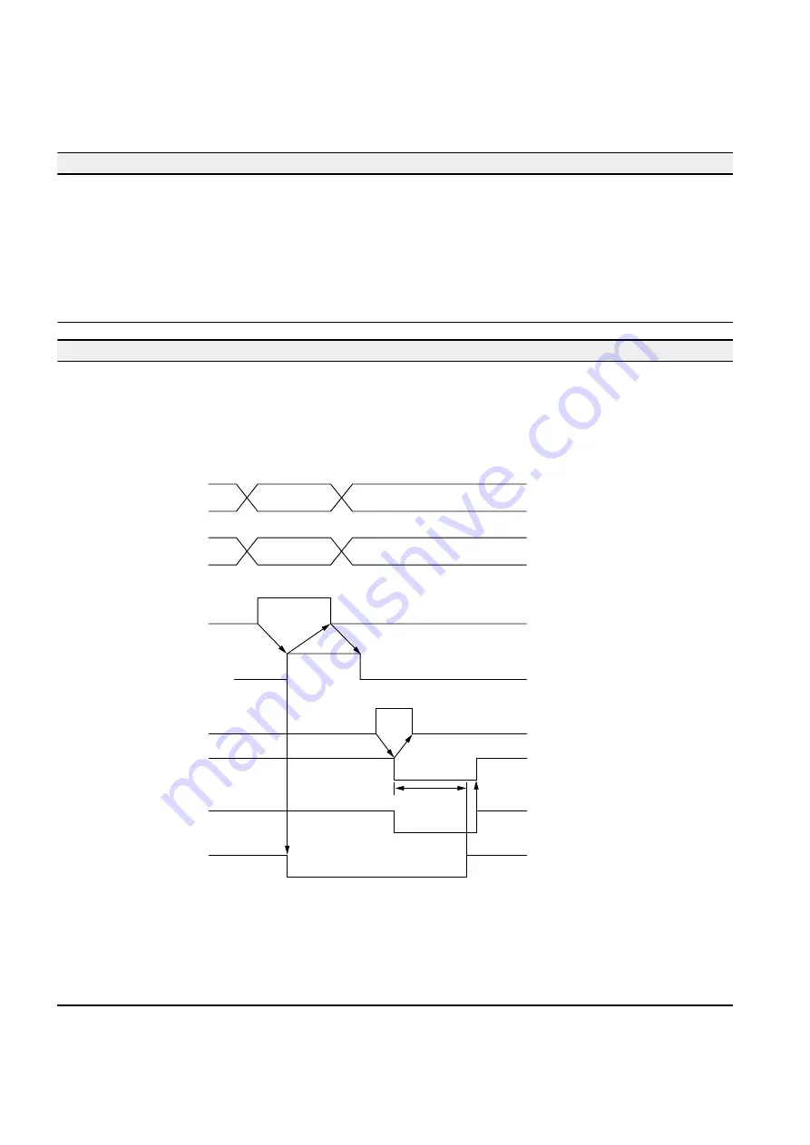
• In pulse generation mode, the status of this signal becomes “1” (one) when the “command pulse register” is “0”
(zero) and the FIFO buffer is cleared.
The status of the “command pulse register” becomes “1” (one) when pulse output is completed or when command
pulse register reset signal is issued.
Select register
(PC == > MP1)
Set value data
(PC == > MP1)
Write command
(PC == > MP1)
Response to write
command (PC <== MP1)
Start command
(PC == > MP1)
Positioning end
(PC <== MP1)
Command pulse
zero (PC <== MP1)
Near-zero
(PC <== MP1)
“1”
(10,000)
(00011)
“1”
“1”
“1”
“1”
“1”
“1”
“1”
“1”
Pulse
outputting
· In the position command mode
· Becomes “0” while pulse is output
Precaution:
With this module, positioning data can be registered in the FIFO buffer.
The command pulse zero signal becomes “0” while unexecuted positioning data exists in the FIFO buffer.
When positioning by the data registered in the FIFO buffer has all been completed or when the command pulse
register reset command is issued, the FIFO buffer becomes free.
5-2 NP1F-MP1 I/O Area
Summary of Contents for micrex-sx NP1F-MP1
Page 1: ...FEH214a series USER S MANUAL PULSE TRAIN POSITIONING CONTROL COMBINED MODULE...
Page 28: ...3 10 3 4 Dimensions 3 4 1 NP1F MP1 for 1 axis 3 4 2 NP1F MP2 for 2 axes 90 46 5 75 35 105...
Page 29: ...3 11 3 4 Dimensions 3 4 3 NP2F LEV Signal converter 95 47 2 10 29 8 39 8 85 95 40 36 6...
Page 223: ...Section 8 Troubleshooting Page 8 1 LED Indication 8 1 8 2 Error Indication 8 2...


