


7-18
7-3 Functions of Pulse Generation Mode
Points of use:
· To use the original point return function with OT in the returning direction or in the reverse direction, or to use
the preset function which makes the current position the machine origin, it is necessary to adapt to these
functions by the application on the CPU module side.
· If only shift length is specified for returning to the original point by the servo system, displacement may occur
depending on the deviation amount of the deviation counter on the servo amplifier side.
Referencing the deviation amount when phase-Z was detected from this module (NP1F-MP1/MP2), execute
original point return according to the procedure shown below:
1) Set the number of pulses which is half the shift length to the original point in the command pulse register
and then start this function.
2) When phase-Z is detected, add the following value to the command pulse register.
The value to be added = (Set value of shift length)/2 - (Deviation amount)
3) When the deviation amount is greater than 1/2 of the set value of the shift length, even if the value to be
added is set to “0,” an overrun occurs, passing the target position when stopped.
(In such cases, decrease the creep speed.)
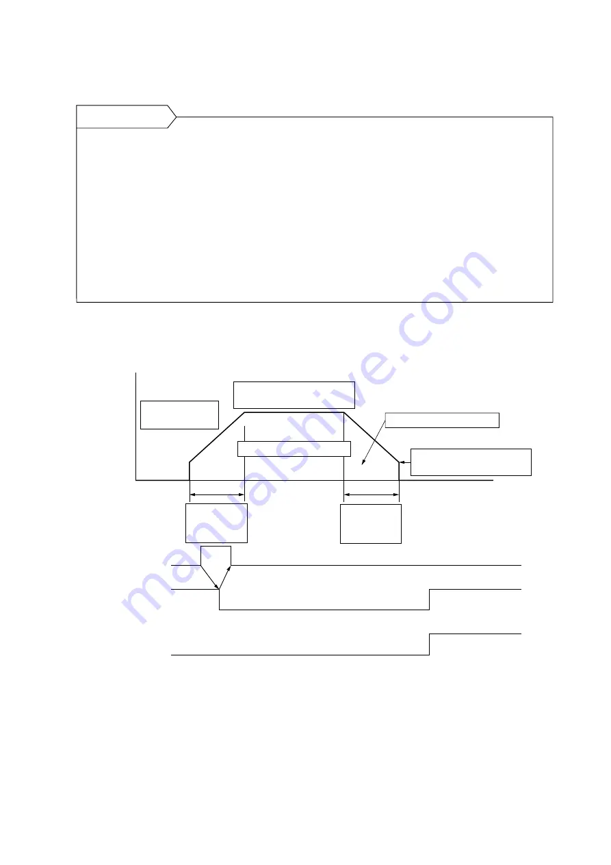
7-3-13 Positioning operation
• Write the necessary data in each register and then set the start command to “1.”
Frequency
Time
“1”
Start command
(PC == > MP1/MP2)
“1”
“1”
Positioning end
(PC <== MP1/MP2)
“1”
Command pulse zero
(PC <== MP1/MP2)
Current frequency
register
Target frequency register
Speed multiplication register
Acceleration/
deceleration
register
Acceleration/
deceleration
register
Base frequency register
Speed multiplication register
Command pulse register
Deceleration point register
Acceleration/deceleration register : Controls the acceleration/deceleration time (acceleration).
Target frequency register
: Controls the pulse output frequency.
Base frequency register
: Controls the automatic-start frequency.
Current frequency register
: Controls the measured value of command frequency.
Speed multiplication register
: Controls the maximum frequency.
Command pulse register
: Controls the number of pulses which are output from the pulse generator.
Remaining pulses are stored in this register.
Deceleration point register
: Controls the deceleration starting point.
Command pulse zero
: Becomes “1” when the number of pulses remaining in the command pulse
register is “0.”
Summary of Contents for micrex-sx NP1F-MP1
Page 1: ...FEH214a series USER S MANUAL PULSE TRAIN POSITIONING CONTROL COMBINED MODULE...
Page 28: ...3 10 3 4 Dimensions 3 4 1 NP1F MP1 for 1 axis 3 4 2 NP1F MP2 for 2 axes 90 46 5 75 35 105...
Page 29: ...3 11 3 4 Dimensions 3 4 3 NP2F LEV Signal converter 95 47 2 10 29 8 39 8 85 95 40 36 6...
Page 223: ...Section 8 Troubleshooting Page 8 1 LED Indication 8 1 8 2 Error Indication 8 2...


