17
TN4FCXA2
j
-EDF-
E
Connection mechanism
Connecting the transmitter to the pipes.
(1)
In general, the pipes are connected to the transmitter via the isolation valves or a manifold.
In this last case, the manifold must be fixed to the transmitter with 4 suitable screws (7/16-
20UNF), and the pipes must be connected to the manifold. Apply a tightening torque on
these bolts between 30 and 40 N.m
(2)
If not using a valve or manifold, the pipes will be directly linked to the transmitter. If the threads
between the transmitter and the pipes are different, use an oval flange.
Position of the fitting mechanism
The element generating the differential pressure must be adapted so that this pressure is correctly
transmitted to the transmitter. The positions of the fitting mechanism are determined based on
of the conditions of service (measuring point, process characteristics).
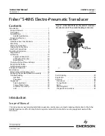
Observe the following mounting positions depending of the process:
Gas measurement
Liquid measurement
From 0 to 45° toward the
top relative to the vertical
From 0 to 45° toward the bottom
relative to the horizontal
From 0 to 45° toward the
top relative to the horizontal
Steam measurement
45
ϒ
45
ϒ
45
ϒ
45
ϒ
45
ϒ
45
ϒ
TOP
TOP
BOTTOM
BOTTOM
3.2.1 Differential pressure and flow transmitters (FKC)
Locate the “high” and “low” pressure sides of the transmitter.
The high pressure side is indicated by
H
and the low pressure side by
L
on the neck of the cell.
Remove the protective plugs.
The connection mechanisms are protected by the plastic plugs.
Do not forget to remove them before the pipes are connected. Be careful not to damage the
threads or the supports of the seal.
The connection of the pipelines to the transmitter must comply with certain rules to generate a
properly precise measurement:
(1) The transmitter must be installed below the piping for the steam and liquid mechanisms.
(2) The transmitter must be installed above the piping for the gas mechanisms.
The choice of the manifolds in the installation is done according to the maximum
pressure conditions of the process (the accessories such as manifolds and
valves are provided by the user). Process leaks from these components can
distort the measurement.
ATTENTION
Orifice plate