


Debugger Engine Environment Variables
Local Configuration File (usually project.ini)
845
Microcontrollers Debugger Manual
Default Layout Configuration
(
PROJECT.INI
)
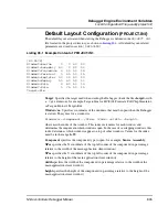
The default layout activated when starting the Debugger is defined in the
PROJECT.INI
file located in the project directory, as shown in
Listing 35.1
. All default layout-related
parameters are stored in section
[DEFAULTS]
.
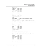
Listing 35.1 Example Content of PROJECT.INI:
[HI-WAVE]
Window0=Source 0 0 60 30
Window1=Assembly 60 0 40 30
Window2=Procedure 0 30 50 15
Window3=Terminal 0 45 50 15
Window4=Register 50 30 50 30
Window5=Memory 50 60 50 30
Window6=Data 0 60 50 15
Window7=Data 0 75 50 15
Target=Sim
Target
: Specifies the target used when starting the Debugger (loads the file
<target>
with
a
.tgt
extension), for example, Target=Sim for HC(S)08 Freescale Full Chip Simulator,
or Target=Motosil, Target=Bdi.
Window<n>
: Specifies coordinates of the windows that must be open when the Debugger
is started. The syntax for a window is:
Window<n>=<component> <XPos> <YPos> <width> <height>
where
n
is the index of the window. This index increments for each window and
determines the sequence in which windows open. In the case of overlapping windows, this
index determines which windows appear on top of other windows. Values for the index
must be in the range
0–99
.
Component
specifies the component type to open, for example,
Source
,
Assembly
.
XPos
specifies the X coordinate of the top left corner of the component (in percentage
relative to the width of the main application client window).
YPos
specifies the Y coordinate of the top left corner of the component (in percentage
relative to the height of the main application client window).
width
specifies the width of the component (in percentage relative to the width of the
main application client window).
height
specifies the height of the component (in percentage relative to the height of the
main application client window).
Summary of Contents for Microcontrollers
Page 1: ...Microcontrollers Debugger Manual Revised 22 October 2007 ...
Page 20: ...Table of Contents 20 Microcontrollers Debugger Manual ...
Page 24: ...Book I Contents 24 Microcontrollers Debugger Manual ...
Page 60: ...Debugger Interface Highlights of the User Interface 60 Microcontrollers Debugger Manual ...
Page 156: ...Debugger Components Visualization Utilities 156 Microcontrollers Debugger Manual ...
Page 198: ...Real Time Kernel Awareness OSEK Kernel Awareness 198 Microcontrollers Debugger Manual ...
Page 236: ...Synchronized Debugging Through DA C IDE Troubleshooting 236 Microcontrollers Debugger Manual ...
Page 238: ...Book II Contents 238 Microcontrollers Debugger Manual ...
Page 332: ...HC08 Full Chip Simulation Configuration Procedure 332 Microcontrollers Debugger Manual ...
Page 348: ...MON08 Interface Connection Device Class Description 348 Microcontrollers Debugger Manual ...
Page 364: ...ICS MON08 Interface Connection Device Class Description 364 Microcontrollers Debugger Manual ...
Page 428: ...HC08 FSICEBASE Emulator Bus State Analyzer BSA 428 Microcontrollers Debugger Manual ...
Page 430: ...Book III Contents 430 Microcontrollers Debugger Manual ...
Page 466: ...HCS08 Full Chip Simulation Peripheral Modules Commands 466 Microcontrollers Debugger Manual ...
Page 544: ...HCS08 On Chip DBG Module HCS08 DBG V3 New Features 544 Microcontrollers Debugger Manual ...
Page 546: ...Book IV Contents 546 Microcontrollers Debugger Manual ...
Page 576: ...Book V Contents 576 Microcontrollers Debugger Manual ...
Page 698: ...Book VI Contents 698 Microcontrollers Debugger Manual ...
Page 714: ...Flash Programming NVMC Commands 714 Microcontrollers Debugger Manual ...
Page 730: ...Book VII Contents 730 Microcontrollers Debugger Manual ...
Page 840: ...Book VIII Contents 840 Microcontrollers Debugger Manual ...
Page 864: ...Book IX Contents 864 Microcontrollers Debugger Manual ...
Page 868: ...Legacy Target Interfaces Removed 868 Microcontrollers Debugger Manual ...