


Real Time Kernel Awareness
OSEK Kernel Awareness
196
Microcontrollers Debugger Manual
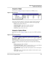
•
Current Value
: displays the current value of the system timer.
•
Activated Alarm
: displays associated alarms.
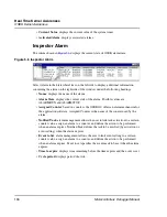
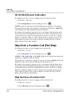
Inspector Alarm
The Alarm shown in
Figure 5.6
displays the current state of OSEK alarm trace.
Figure 5.6 Inspector Alarm
Select Alarm in the hierarchical tree on the left side to display additional information
concerning the alarm on the right side of the window under the following headings:
•
Name
: displays the name of the alarm.
•
Alarm State
: displays the current state of the alarm. Possible values are
ALARMRUN and ALARMSTOP.
•
Assigned Counter
: based on counters, the OSEK OS offers an alarm mechanism for
the application software. Assigned Counter is the name of the counter used by the
alarm.
•
Notified Task
: alarm management allows the user to link task activation to a certain
counter value, assign an alarm to a counter, and define the action to be performed
when an alarm expires. Notified Task defines the task to be notified (by activation or
event setting) when the alarm expires.
•
Event to Set
: alarm management allows the user to link event setting to a certain
counter value, assign an alarm to a counter, and define the action to be performed
when an alarm expires. Event to set specifies the event mask to be set when the alarm
expires.
•
Time to expire
: displays time remaining before the time expires and the event is set.
•
Cycle period
: displays period of a tick.
Summary of Contents for Microcontrollers
Page 1: ...Microcontrollers Debugger Manual Revised 22 October 2007 ...
Page 20: ...Table of Contents 20 Microcontrollers Debugger Manual ...
Page 24: ...Book I Contents 24 Microcontrollers Debugger Manual ...
Page 60: ...Debugger Interface Highlights of the User Interface 60 Microcontrollers Debugger Manual ...
Page 156: ...Debugger Components Visualization Utilities 156 Microcontrollers Debugger Manual ...
Page 198: ...Real Time Kernel Awareness OSEK Kernel Awareness 198 Microcontrollers Debugger Manual ...
Page 236: ...Synchronized Debugging Through DA C IDE Troubleshooting 236 Microcontrollers Debugger Manual ...
Page 238: ...Book II Contents 238 Microcontrollers Debugger Manual ...
Page 332: ...HC08 Full Chip Simulation Configuration Procedure 332 Microcontrollers Debugger Manual ...
Page 348: ...MON08 Interface Connection Device Class Description 348 Microcontrollers Debugger Manual ...
Page 364: ...ICS MON08 Interface Connection Device Class Description 364 Microcontrollers Debugger Manual ...
Page 428: ...HC08 FSICEBASE Emulator Bus State Analyzer BSA 428 Microcontrollers Debugger Manual ...
Page 430: ...Book III Contents 430 Microcontrollers Debugger Manual ...
Page 466: ...HCS08 Full Chip Simulation Peripheral Modules Commands 466 Microcontrollers Debugger Manual ...
Page 544: ...HCS08 On Chip DBG Module HCS08 DBG V3 New Features 544 Microcontrollers Debugger Manual ...
Page 546: ...Book IV Contents 546 Microcontrollers Debugger Manual ...
Page 576: ...Book V Contents 576 Microcontrollers Debugger Manual ...
Page 698: ...Book VI Contents 698 Microcontrollers Debugger Manual ...
Page 714: ...Flash Programming NVMC Commands 714 Microcontrollers Debugger Manual ...
Page 730: ...Book VII Contents 730 Microcontrollers Debugger Manual ...
Page 840: ...Book VIII Contents 840 Microcontrollers Debugger Manual ...
Page 864: ...Book IX Contents 864 Microcontrollers Debugger Manual ...
Page 868: ...Legacy Target Interfaces Removed 868 Microcontrollers Debugger Manual ...