

Debugger Components
General Debugger Components
84
Microcontrollers Debugger Manual
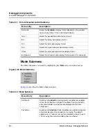
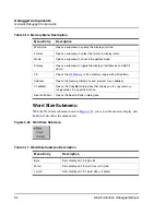
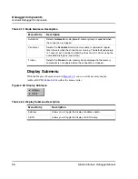
Mode Submenu
The Mode Submenu is activated by highlighting the
Mode
entry on the Data menu:
Figure 3.24 Mode Submenu
Table 3.12
describes the Mode submenu entries.
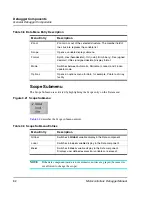
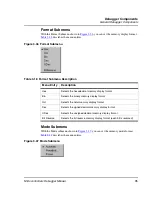
Table 3.11 Format Selected and All Submenu
Menu entry
Description
Symbolic
Select the
Symbolic
(display format depends on the variable
type) display format. This is the default display.
Hex
Select the hexadecimal data display format
Bin
Select the binary data display format
Oct
Select the octal data display format
Dec
Select the signed decimal data display format
UDec
Select the unsigned decimal data display format
Bit Reverse
Select the bit reverse data display format (each bit is reversed).
Table 3.12 Mode Submenu
Menu Entry
Description
Automatic
Switches to
Automatic
mode (default); variables are updated
when the connection is stopped. Variables from the currently
executed module or procedure are displayed in the data
component.
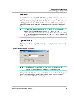
Periodical
Switches to
Periodical
mode; variables are updated at regular
time intervals when the connection is running. The default
update rate is 1 second, but can be modified by steps of up to
100 ms using the associated dialog box (see below).
Summary of Contents for Microcontrollers
Page 1: ...Microcontrollers Debugger Manual Revised 22 October 2007 ...
Page 20: ...Table of Contents 20 Microcontrollers Debugger Manual ...
Page 24: ...Book I Contents 24 Microcontrollers Debugger Manual ...
Page 60: ...Debugger Interface Highlights of the User Interface 60 Microcontrollers Debugger Manual ...
Page 156: ...Debugger Components Visualization Utilities 156 Microcontrollers Debugger Manual ...
Page 198: ...Real Time Kernel Awareness OSEK Kernel Awareness 198 Microcontrollers Debugger Manual ...
Page 236: ...Synchronized Debugging Through DA C IDE Troubleshooting 236 Microcontrollers Debugger Manual ...
Page 238: ...Book II Contents 238 Microcontrollers Debugger Manual ...
Page 332: ...HC08 Full Chip Simulation Configuration Procedure 332 Microcontrollers Debugger Manual ...
Page 348: ...MON08 Interface Connection Device Class Description 348 Microcontrollers Debugger Manual ...
Page 364: ...ICS MON08 Interface Connection Device Class Description 364 Microcontrollers Debugger Manual ...
Page 428: ...HC08 FSICEBASE Emulator Bus State Analyzer BSA 428 Microcontrollers Debugger Manual ...
Page 430: ...Book III Contents 430 Microcontrollers Debugger Manual ...
Page 466: ...HCS08 Full Chip Simulation Peripheral Modules Commands 466 Microcontrollers Debugger Manual ...
Page 544: ...HCS08 On Chip DBG Module HCS08 DBG V3 New Features 544 Microcontrollers Debugger Manual ...
Page 546: ...Book IV Contents 546 Microcontrollers Debugger Manual ...
Page 576: ...Book V Contents 576 Microcontrollers Debugger Manual ...
Page 698: ...Book VI Contents 698 Microcontrollers Debugger Manual ...
Page 714: ...Flash Programming NVMC Commands 714 Microcontrollers Debugger Manual ...
Page 730: ...Book VII Contents 730 Microcontrollers Debugger Manual ...
Page 840: ...Book VIII Contents 840 Microcontrollers Debugger Manual ...
Page 864: ...Book IX Contents 864 Microcontrollers Debugger Manual ...
Page 868: ...Legacy Target Interfaces Removed 868 Microcontrollers Debugger Manual ...