

HC08 FSICEBASE Emulator
Setting Up Logic Cables and Connectors
419
Microcontrollers Debugger Manual
Emulation System Reset
The debugger allows you to reset the emulation MCU and set the PC register to the
contents of the reset vector.
To reset the FSICEBASE:
1. If the FSICEBASE is connected to an emulator module (EM), specify the type of reset
available to the EM.
a. From debugger main menu, select
FSICEBASE-HC08
The FSICEBASE-HC08 menu is between the Run menu and the Component
menu. If you do not see the FSICEBASE-HC08 menu, you need to specify the
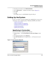
connection. For more information on specifying a connection see
Specifying A
Connection
.
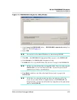
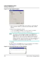
b. Select
Target Signals
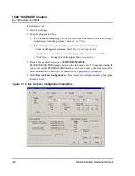
— Target Signals dialog box opens (
Figure 17.8
)
c. If you want to allow a reset signal coming from the target system (through the
target cable), check the
Reset IN
checkbox.
Some EMs include a hardware jumper that governs target resets. Make sure to
configure jumpers as necessary to use the
Reset IN
option. For more information,
refer to your EM’s documentation.
d. To allow a reset signal to be sent to the target system (through the target cable),
check the
Reset Out
checkbox.
NOTE
If you check both
Reset IN
and
Reset Out
the internal resets of the emulator
system are not sent to the target system.
e. Click
OK
2. From debugger main menu, select
FSCICEBASE-HC08
3. Select
Reset
The debugger sends a reset signal to the FSICEBASE.
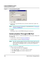
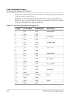
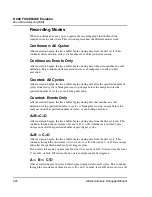
Setting Up Logic Cables and Connectors
The diagram below shows the pin numbering for both pod A and pod B logic cable
connectors of the station module.
Table 17.1
shows the pinout information of the logic
clips. You can use the logic clips are used to capture data in the bus state analyzer. (Pin 9
of both pods provides connection to an external ground.) In addition, the pod connectors
are used as external clock inputs for the emulator clock and bus state analyzer timetag.
The table also provides color code information for each pod. The external clock inputs are
through pin 17 of each pod. Pod A pin 17 is the external clock input for the emulator. To
Summary of Contents for Microcontrollers
Page 1: ...Microcontrollers Debugger Manual Revised 22 October 2007 ...
Page 20: ...Table of Contents 20 Microcontrollers Debugger Manual ...
Page 24: ...Book I Contents 24 Microcontrollers Debugger Manual ...
Page 60: ...Debugger Interface Highlights of the User Interface 60 Microcontrollers Debugger Manual ...
Page 156: ...Debugger Components Visualization Utilities 156 Microcontrollers Debugger Manual ...
Page 198: ...Real Time Kernel Awareness OSEK Kernel Awareness 198 Microcontrollers Debugger Manual ...
Page 236: ...Synchronized Debugging Through DA C IDE Troubleshooting 236 Microcontrollers Debugger Manual ...
Page 238: ...Book II Contents 238 Microcontrollers Debugger Manual ...
Page 332: ...HC08 Full Chip Simulation Configuration Procedure 332 Microcontrollers Debugger Manual ...
Page 348: ...MON08 Interface Connection Device Class Description 348 Microcontrollers Debugger Manual ...
Page 364: ...ICS MON08 Interface Connection Device Class Description 364 Microcontrollers Debugger Manual ...
Page 428: ...HC08 FSICEBASE Emulator Bus State Analyzer BSA 428 Microcontrollers Debugger Manual ...
Page 430: ...Book III Contents 430 Microcontrollers Debugger Manual ...
Page 466: ...HCS08 Full Chip Simulation Peripheral Modules Commands 466 Microcontrollers Debugger Manual ...
Page 544: ...HCS08 On Chip DBG Module HCS08 DBG V3 New Features 544 Microcontrollers Debugger Manual ...
Page 546: ...Book IV Contents 546 Microcontrollers Debugger Manual ...
Page 576: ...Book V Contents 576 Microcontrollers Debugger Manual ...
Page 698: ...Book VI Contents 698 Microcontrollers Debugger Manual ...
Page 714: ...Flash Programming NVMC Commands 714 Microcontrollers Debugger Manual ...
Page 730: ...Book VII Contents 730 Microcontrollers Debugger Manual ...
Page 840: ...Book VIII Contents 840 Microcontrollers Debugger Manual ...
Page 864: ...Book IX Contents 864 Microcontrollers Debugger Manual ...
Page 868: ...Legacy Target Interfaces Removed 868 Microcontrollers Debugger Manual ...