

Debugger Components
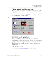
Visualization Utilities
151
Microcontrollers Debugger Manual
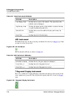
7-Segment Display instrument attributes are shown in
Table 3.53
.
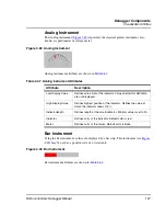
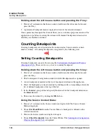
Switch Instrument
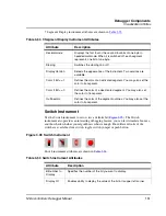
Use the Switch instrument to set or view a definite bit (
Figure 3.95
). The Switch
instrument also provides an interesting debugging feature; you can let it simulate bounces,
and thus check whether your algorithm is robust enough. Four different looks of the
switch are available: slide switch, toggle switch, jumper or push button.
Figure 3.95 Switch Instrument
Switch instrument attributes are shown in
Table 3.54
.
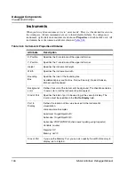
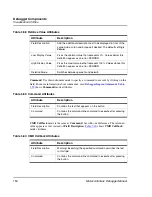
Table 3.53 7-Segment Display Instrument Attributes
Attribute
Description
Decimalmode
Displays the first four or the second four bits of one byte in
hexadecimal mode. When it is switched off, each segment
represents one bit of one byte.
Sloping
Switches the sloping on or off.
Display Version
Selects the appearance of the instrument. Two versions are
available.
Color if Bit = = 1
Defines the color of an activated segment. You may also set the
color to transparent.
Color if Bit = = 0
Defines the color of a deactivated segment. You may also set
the color to transparent.
Outlinecolor
Defines the color of the segment outlines. You may also set the
color to transparent.
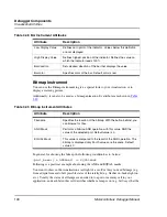
Table 3.54 Switch Instrument Attributes
Attribute
Description
Bitnumber to
Display
Specifies the number of the bit you want to display.
Display 0/1
Enables ability to display the value of the bit in its upper left corner.
Summary of Contents for Microcontrollers
Page 1: ...Microcontrollers Debugger Manual Revised 22 October 2007 ...
Page 20: ...Table of Contents 20 Microcontrollers Debugger Manual ...
Page 24: ...Book I Contents 24 Microcontrollers Debugger Manual ...
Page 60: ...Debugger Interface Highlights of the User Interface 60 Microcontrollers Debugger Manual ...
Page 156: ...Debugger Components Visualization Utilities 156 Microcontrollers Debugger Manual ...
Page 198: ...Real Time Kernel Awareness OSEK Kernel Awareness 198 Microcontrollers Debugger Manual ...
Page 236: ...Synchronized Debugging Through DA C IDE Troubleshooting 236 Microcontrollers Debugger Manual ...
Page 238: ...Book II Contents 238 Microcontrollers Debugger Manual ...
Page 332: ...HC08 Full Chip Simulation Configuration Procedure 332 Microcontrollers Debugger Manual ...
Page 348: ...MON08 Interface Connection Device Class Description 348 Microcontrollers Debugger Manual ...
Page 364: ...ICS MON08 Interface Connection Device Class Description 364 Microcontrollers Debugger Manual ...
Page 428: ...HC08 FSICEBASE Emulator Bus State Analyzer BSA 428 Microcontrollers Debugger Manual ...
Page 430: ...Book III Contents 430 Microcontrollers Debugger Manual ...
Page 466: ...HCS08 Full Chip Simulation Peripheral Modules Commands 466 Microcontrollers Debugger Manual ...
Page 544: ...HCS08 On Chip DBG Module HCS08 DBG V3 New Features 544 Microcontrollers Debugger Manual ...
Page 546: ...Book IV Contents 546 Microcontrollers Debugger Manual ...
Page 576: ...Book V Contents 576 Microcontrollers Debugger Manual ...
Page 698: ...Book VI Contents 698 Microcontrollers Debugger Manual ...
Page 714: ...Flash Programming NVMC Commands 714 Microcontrollers Debugger Manual ...
Page 730: ...Book VII Contents 730 Microcontrollers Debugger Manual ...
Page 840: ...Book VIII Contents 840 Microcontrollers Debugger Manual ...
Page 864: ...Book IX Contents 864 Microcontrollers Debugger Manual ...
Page 868: ...Legacy Target Interfaces Removed 868 Microcontrollers Debugger Manual ...