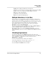
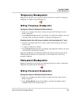
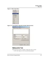

Control Points
Setting Breakpoints
167
Microcontrollers Debugger Manual
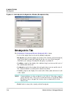
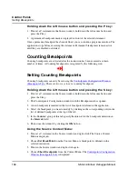
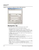
5. Select the breakpoint you want to modify by clicking on the corresponding entry in the
list of defined breakpoints at the top of the tab.
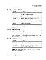
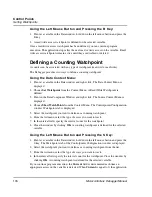
6. In the
Counter:
group of this tab specify the interval for the breakpoint detection in
the
Interval:
field.
7. Then close the window by clicking the
OK
button.
If you continue program execution, the content of the
Current:
field is decremented each
time the instruction containing the breakpoint is reached. When
Current
is equal to 0, the
application stops. If the checkbox
Temporary
is unchecked (not a temporary breakpoint),
Current
is reloaded with the value stored in
Interval:
in order to enable the counting
breakpoint again.
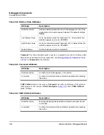
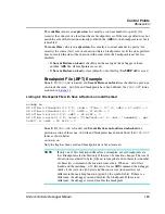
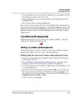
Conditional Breakpoints
Conditional breakpoints are activated when a given condition is TRUE. A conditional
breakpoint is recognized by the following icon:
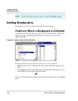
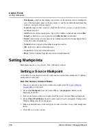
Setting Conditional Breakpoints
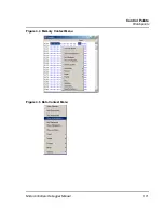
Conditional breakpoints can only be set from the Controlpoint Configuration window’s
Breakpoints tab. There are two ways to set a conditional breakpoint:
Holding down the left mouse button and pressing the S key:
1. Point at a C statement in the Source Component window, hold down the left mouse
button and press the S key.
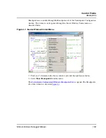
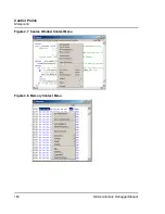
2. The
Controlpoints Configuration Window (Breakpoints Tab)
is opened and a new
breakpoint is inserted in the list of breakpoints defined in the application.
3. Select the breakpoint you want to modify by clicking on the corresponding entry in the
list of defined breakpoints.
4. Specify the condition for breakpoint activation in the
Condition
: group Condition box.
The condition must be specified using the ANSI C syntax (Example
counter = = 7
).
You can use register values in the breakpoint condition field with the following syntax:
$RegisterName
(Example
$RX = = 0x10
)
5. Close the window by clicking
OK
.
Summary of Contents for Microcontrollers
Page 1: ...Microcontrollers Debugger Manual Revised 22 October 2007 ...
Page 20: ...Table of Contents 20 Microcontrollers Debugger Manual ...
Page 24: ...Book I Contents 24 Microcontrollers Debugger Manual ...
Page 60: ...Debugger Interface Highlights of the User Interface 60 Microcontrollers Debugger Manual ...
Page 156: ...Debugger Components Visualization Utilities 156 Microcontrollers Debugger Manual ...
Page 198: ...Real Time Kernel Awareness OSEK Kernel Awareness 198 Microcontrollers Debugger Manual ...
Page 236: ...Synchronized Debugging Through DA C IDE Troubleshooting 236 Microcontrollers Debugger Manual ...
Page 238: ...Book II Contents 238 Microcontrollers Debugger Manual ...
Page 332: ...HC08 Full Chip Simulation Configuration Procedure 332 Microcontrollers Debugger Manual ...
Page 348: ...MON08 Interface Connection Device Class Description 348 Microcontrollers Debugger Manual ...
Page 364: ...ICS MON08 Interface Connection Device Class Description 364 Microcontrollers Debugger Manual ...
Page 428: ...HC08 FSICEBASE Emulator Bus State Analyzer BSA 428 Microcontrollers Debugger Manual ...
Page 430: ...Book III Contents 430 Microcontrollers Debugger Manual ...
Page 466: ...HCS08 Full Chip Simulation Peripheral Modules Commands 466 Microcontrollers Debugger Manual ...
Page 544: ...HCS08 On Chip DBG Module HCS08 DBG V3 New Features 544 Microcontrollers Debugger Manual ...
Page 546: ...Book IV Contents 546 Microcontrollers Debugger Manual ...
Page 576: ...Book V Contents 576 Microcontrollers Debugger Manual ...
Page 698: ...Book VI Contents 698 Microcontrollers Debugger Manual ...
Page 714: ...Flash Programming NVMC Commands 714 Microcontrollers Debugger Manual ...
Page 730: ...Book VII Contents 730 Microcontrollers Debugger Manual ...
Page 840: ...Book VIII Contents 840 Microcontrollers Debugger Manual ...
Page 864: ...Book IX Contents 864 Microcontrollers Debugger Manual ...
Page 868: ...Legacy Target Interfaces Removed 868 Microcontrollers Debugger Manual ...