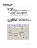


HC08 FSICEBASE Emulator
Bus State Analyzer (BSA)
424
Microcontrollers Debugger Manual
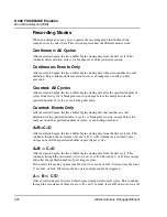
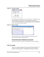
Recording Modes
When you define an event, you can specify the recording mode that the Bus State
Analyzer uses to collect data. This section explains how the different modes work.
Continuous: All Cycles
After execution begins, the trace buffer begins storing data from the first cycle. This
continues until execution arrives at a breakpoint, or until you halt execution.
Continuous: Events Only
After execution begins, the trace buffer begins storing data when data matches an event
definition. This continues until execution arrives at a breakpoint, or until you halt
execution.
Counted: All Cycles
After execution begins, the trace buffer begins storing data after the specified number of
cycles from first cycle. A breakpoint can stop storage before the analyzer stores the
specified number of cycles, as can halting execution.
Counted: Events Only
After execution begins, the trace buffer begins storing data that matches an event
definition for the specified number of cycles. A breakpoint can stop storage before the
analyzer stores the specified number of cycles; as can halting execution.
A+B+C+D
After execution begins, the trace buffer begins storing data from the first cycle run. This
continues through the occurrence of event A, B, C, or D (whichever is enabled); data
storage ends after the specified number of post-trigger cycles.
A+B -> C+D
After execution begins, the trace buffer begins storing data from the first cycle. This
continues through the occurrence of two events: A or B, followed by C or D. Data storage
ends after the specified number of post-trigger cycles.
If you select this mode, you must enable event A, event B, or both. You must enable event
C, event D, or both. Otherwise, the bus state analyzer cannot be triggered.
A -> B -> C !D
After execution begins, the trace buffer begins storing data from all cycles. This continues
through the occurrence of three events, A, B, and C, in order, if event D does not occur. (If
Summary of Contents for Microcontrollers
Page 1: ...Microcontrollers Debugger Manual Revised 22 October 2007 ...
Page 20: ...Table of Contents 20 Microcontrollers Debugger Manual ...
Page 24: ...Book I Contents 24 Microcontrollers Debugger Manual ...
Page 60: ...Debugger Interface Highlights of the User Interface 60 Microcontrollers Debugger Manual ...
Page 156: ...Debugger Components Visualization Utilities 156 Microcontrollers Debugger Manual ...
Page 198: ...Real Time Kernel Awareness OSEK Kernel Awareness 198 Microcontrollers Debugger Manual ...
Page 236: ...Synchronized Debugging Through DA C IDE Troubleshooting 236 Microcontrollers Debugger Manual ...
Page 238: ...Book II Contents 238 Microcontrollers Debugger Manual ...
Page 332: ...HC08 Full Chip Simulation Configuration Procedure 332 Microcontrollers Debugger Manual ...
Page 348: ...MON08 Interface Connection Device Class Description 348 Microcontrollers Debugger Manual ...
Page 364: ...ICS MON08 Interface Connection Device Class Description 364 Microcontrollers Debugger Manual ...
Page 428: ...HC08 FSICEBASE Emulator Bus State Analyzer BSA 428 Microcontrollers Debugger Manual ...
Page 430: ...Book III Contents 430 Microcontrollers Debugger Manual ...
Page 466: ...HCS08 Full Chip Simulation Peripheral Modules Commands 466 Microcontrollers Debugger Manual ...
Page 544: ...HCS08 On Chip DBG Module HCS08 DBG V3 New Features 544 Microcontrollers Debugger Manual ...
Page 546: ...Book IV Contents 546 Microcontrollers Debugger Manual ...
Page 576: ...Book V Contents 576 Microcontrollers Debugger Manual ...
Page 698: ...Book VI Contents 698 Microcontrollers Debugger Manual ...
Page 714: ...Flash Programming NVMC Commands 714 Microcontrollers Debugger Manual ...
Page 730: ...Book VII Contents 730 Microcontrollers Debugger Manual ...
Page 840: ...Book VIII Contents 840 Microcontrollers Debugger Manual ...
Page 864: ...Book IX Contents 864 Microcontrollers Debugger Manual ...
Page 868: ...Legacy Target Interfaces Removed 868 Microcontrollers Debugger Manual ...