


ColdFire V1 Full Chip Simulation Connection
True Time I/O Stimulation
643
Microcontrollers Debugger Manual
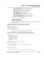
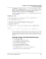
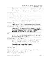
VECTOR 7 Interrupt_Function /* set vector on Interrupt 7 */
If the
prm
file does not specify the interrupt vector address, the FCS stops when
interruption is generated. The exception mnemonic (matching the interrupt vector number)
appears in the FCS status bar.
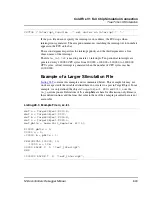
The second argument specifies the interrupt priority and the third argument is a free
chosen name of the interrupt.
The file
io_int.txt
is used to generate 11 interrupts. Ten periodical interrupts are
generated every 100,000 CPU cycles from 200,000 + 100,000 = 300,000 to 1,200,000
CPU cycles. A final interrupt is generated when the number of CPU cycles reaches
10,000,000.
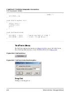
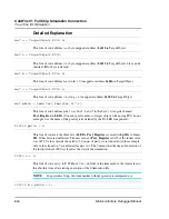
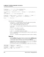
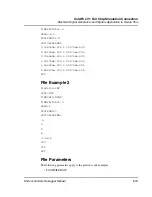
Example of a Larger Stimulation File
Listing 28.9
contains this example and is commented below. This example file may not
work as expected if the variables defined here do not refer to a port in TargetObject. In our
example, we only defined the objects
TargetObject.#210
and
#212
over the
Io_led
component. Definitions of
b
,
c
and
pbits
are here for illustration only. Remove
these definition lines and the lines that refer to them, if the example presented here is not
executable.
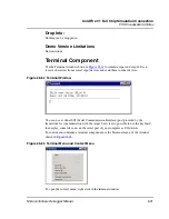
Listing 28.9 Example File io_ex.txt.
def a = TargetObject.#210.B;
def x = TargetObject.#212;
def b = TargetObject.#216.W;
def c = TargetObject.#220.L;
def pbits = Leds.Port_Register.B[7:3];
#10000 pbits = 3;
20000 a = 0;
+20000 b = pbits + 1;
PERIODICAL 100000, 10:
10000 a = 128;
30000 RAISE
7
, 3, "test_interrupt";
END
1000000 RAISE
7
, 3, "test_interrupt";
Summary of Contents for Microcontrollers
Page 1: ...Microcontrollers Debugger Manual Revised 22 October 2007 ...
Page 20: ...Table of Contents 20 Microcontrollers Debugger Manual ...
Page 24: ...Book I Contents 24 Microcontrollers Debugger Manual ...
Page 60: ...Debugger Interface Highlights of the User Interface 60 Microcontrollers Debugger Manual ...
Page 156: ...Debugger Components Visualization Utilities 156 Microcontrollers Debugger Manual ...
Page 198: ...Real Time Kernel Awareness OSEK Kernel Awareness 198 Microcontrollers Debugger Manual ...
Page 236: ...Synchronized Debugging Through DA C IDE Troubleshooting 236 Microcontrollers Debugger Manual ...
Page 238: ...Book II Contents 238 Microcontrollers Debugger Manual ...
Page 332: ...HC08 Full Chip Simulation Configuration Procedure 332 Microcontrollers Debugger Manual ...
Page 348: ...MON08 Interface Connection Device Class Description 348 Microcontrollers Debugger Manual ...
Page 364: ...ICS MON08 Interface Connection Device Class Description 364 Microcontrollers Debugger Manual ...
Page 428: ...HC08 FSICEBASE Emulator Bus State Analyzer BSA 428 Microcontrollers Debugger Manual ...
Page 430: ...Book III Contents 430 Microcontrollers Debugger Manual ...
Page 466: ...HCS08 Full Chip Simulation Peripheral Modules Commands 466 Microcontrollers Debugger Manual ...
Page 544: ...HCS08 On Chip DBG Module HCS08 DBG V3 New Features 544 Microcontrollers Debugger Manual ...
Page 546: ...Book IV Contents 546 Microcontrollers Debugger Manual ...
Page 576: ...Book V Contents 576 Microcontrollers Debugger Manual ...
Page 698: ...Book VI Contents 698 Microcontrollers Debugger Manual ...
Page 714: ...Flash Programming NVMC Commands 714 Microcontrollers Debugger Manual ...
Page 730: ...Book VII Contents 730 Microcontrollers Debugger Manual ...
Page 840: ...Book VIII Contents 840 Microcontrollers Debugger Manual ...
Page 864: ...Book IX Contents 864 Microcontrollers Debugger Manual ...
Page 868: ...Legacy Target Interfaces Removed 868 Microcontrollers Debugger Manual ...