IJ PUMP OPERATION AND MAINTENANCE MANUAL
BO2660-01 6-12
6.4.6 INTERNAL ASSEMBLY
6.4.6.1 Removing Internal Assembly
To remove the internal assembly from the case, proceed as follows:
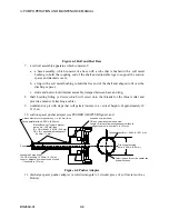
1. Bolt assembly skid or assembly carriage or equivalent device to free end of case. To avoid
subjecting internal assembly to binding or twisting stresses or having it roll off of the track,
ensure:
a. skid or carriage is aligned and leveled with bore of case;
b. flange of skid or carriage presses solidly against the case;
c. feet press against a solid surface across their entire area;
d. skid or carriage is bolted tightly against case, making track completely immobile.
2. Lubricate top of track so that internal assembly will slide easily.
NOTE
The procedure given in step 4, where a pusher adapter is
used to allow a hydraulic ram to push evenly against the
suction spacer (23), is recommended. Pushing or pulling at
the coupling end of the shaft, as outlined in step 5, may
cause bending of the shaft, and should be avoided. Should
you have difficulty in removing the assembly, contact your
nearest Flowserve Sales Office for assistance (see PART
ORDERING AND SERVICING INFORMATION).
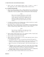
3. To remove internal assembly from case, using hydraulic ram and pusher adapter, proceed as
follows:
a. Being careful not to scratch the shaft, install pusher adapter against suction spacer (23) so
that spacer fins are positioned in cutouts in adapter.
b. Install solid steel block against open end of pusher adapter and set hydraulic ram squarely
against end of block.
c. Place soft cable or nylon lifting strap under pressure reducing sleeve (77), attach hoist
and lift internal assembly slightly to relieve weight from bottom of case.
d. Move assembly completely onto track using hydraulic ram.
e. Move hydraulic ram out of way and remove pusher adapter from shaft.
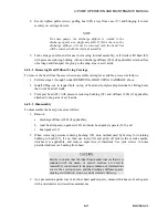
4. To extract internal assembly from pump case using soft cable, proceed as follows:
a. Install eyebolt in coupling end of shaft.
b. Place soft cable or nylon lifting strap under pressure reducing sleeve (77), attach hoist
and lift internal assembly slightly to relieve weight from bottom of case.
CAUTION
To prevent damage to the shaft, apply force straight against
the end of the shaft: there must not be any side forces
exerted on the shaft.
Summary of Contents for IJ
Page 2: ...IJ PUMP INSTALLATION OPERATION MAINTENANCE ...
Page 3: ......
Page 5: ...IJ PUMP OPERATION AND MAINTENANCE MANUAL BO2660 01 iv ...
Page 11: ...IJ PUMP OPERATION AND MAINTENANCE MANUAL BO2660 01 x ...
Page 13: ...IJ PUMP OPERATION AND MAINTENANCE MANUAL BO2660 01 xii ...
Page 17: ...IJ PUMP OPERATION AND MAINTENANCE MANUAL BO2660 01 xvi ...
Page 25: ......
Page 35: ...IJ PUMP OPERATION AND MAINTENANCE MANUAL BO2660 01 2 10 Figure 2 1 Foundation Bolt ...
Page 65: ......
Page 79: ......
Page 83: ......

