IJ PUMP OPERATION AND MAINTENANCE MANUAL
3-21
BO2660-01
NOTE
If your pump is driven by an electric motor with ball
bearings, or by any other driver, then skip to step 5 of this
procedure.
1. See that instructions have been complied with under above headings:
a. DRIVER-TO-PUMP ALIGNMENT PRECONDITIONS, and
b. INSTALLING
COUPLING.
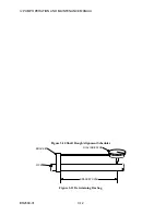
Figure 3-15 Motor Shaft Running Space
2. Set motor on driver pads.
3. Measure total movement of motor shaft as follows:
a. Push shaft into motor case until thrust collar butts against face of bearing as shown by
MOTOR SHAFT RUNNING CLEARANCE figure; then select a reference point on
motor case and mark shaft with pencil.
b. Pull shaft out away from bearing face (i.e., toward pump) as far as it will go; then using
the same reference point that was selected in step a, mark shaft with pencil.
c. Measure distance between pencil marks the distance (or total lateral movement) should
be at least the minimum given in the vendor documentation in the APPENDIX or the
OUTLINE drawing in the back of this manual.
4. Set endspace by pushing shaft back in toward sleeve bearing 0.13 in (3mm) (see MOTOR
SHAFT RUNNING CLEARANCE figure above). At this setting, there will be adequate
endspace between thrust collars and bearing faces. For example, if total lateral movement is
0.5 in (13mm) and the shaft is pushed back in toward bearing face 0.13 in (3mm) as
described, the endspace or clearance is 0.13 in (3mm) on the drive end and 0.37 in (10mm)
on the opposite end.
Summary of Contents for IJ
Page 2: ...IJ PUMP INSTALLATION OPERATION MAINTENANCE ...
Page 3: ......
Page 5: ...IJ PUMP OPERATION AND MAINTENANCE MANUAL BO2660 01 iv ...
Page 11: ...IJ PUMP OPERATION AND MAINTENANCE MANUAL BO2660 01 x ...
Page 13: ...IJ PUMP OPERATION AND MAINTENANCE MANUAL BO2660 01 xii ...
Page 17: ...IJ PUMP OPERATION AND MAINTENANCE MANUAL BO2660 01 xvi ...
Page 25: ......
Page 35: ...IJ PUMP OPERATION AND MAINTENANCE MANUAL BO2660 01 2 10 Figure 2 1 Foundation Bolt ...
Page 65: ......
Page 79: ......
Page 83: ......


