IJ PUMP OPERATION AND MAINTENANCE MANUAL
BO2660-01 3-22
NOTE
After setting endspace the motor shaft should not be moved
prior to scribing location of holddown bolts.
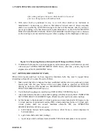
5. With motor shaft as positioned in step 4, or with driver shaft set as instructed in
manufacturer’s instructions, set driver so that distance between ends of driver and pump
shafts is as specified by OUTLINE drawing in the back of this manual. Also if you have a
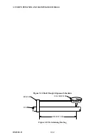
gear-type coupling verify that dimension D equals dimension L as shown by MEASURING
DISTANCE BETWEEN ENDS OF PUMP AND DRIVER SHAFTS figure below. Buttons
as shown in figure are not installed on spacer where couplings are the diaphragm or disk type.
Figure 3-16 Measuring Distance Between Ends Of Pump And Driver Shafts
6. If holddown bolt holes have not been tapped in motor mount pads, you should now proceed
with task (see TAPPING MOTOR MOUNT PADS below); otherwise, you may begin cold
alignment (see COLD ALIGNMENT below).
3.4.7 TAPPING DRIVER MOUNT PADS
Where driver mount pads have not been tapped for holddown bolts, they must be tapped before
attempting to align driver to pump. Proceed as follows:
1. Make certain that driver endspace has been established and that driver is positioned on clean
mount pads with the space between driver and pump shafts as specified on OUTLINE
drawing in the back of this manual (see MEASURING DISTANCE BETWEEN ENDS OF
PUMP AND DRIVER SHAFTS above).
2. Verify that half-couplings are installed (see INSTALLING COUPLING above).
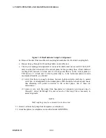
3. Attach dial indicator bracket to driver half-coupling or shaft as shown by DIAL INDICATOR
SETUP FOR SHAFT ALIGNMENT figure. Bracket must be rigid for accurate readings.
4. Set the bracket to the horizontal (9 o'clock) position and rotate both shafts 180 degrees to the
3 o'clock position. Total indicator reading (TIR) in horizontal plane (between 9 o'clock and 3
o'clock points) shall not exceed maximum allowable TIR (see OPERATING
SPECIFICATIONS). If TIR is excessive:
a. hold distance between half-couplings and move driver frame to correct alignment in
horizontal plane;
b. again rotate shafts and check readings;
c. repeat steps a and b until maximum allowable TIR in horizontal plane is not exceeded.
Summary of Contents for IJ
Page 2: ...IJ PUMP INSTALLATION OPERATION MAINTENANCE ...
Page 3: ......
Page 5: ...IJ PUMP OPERATION AND MAINTENANCE MANUAL BO2660 01 iv ...
Page 11: ...IJ PUMP OPERATION AND MAINTENANCE MANUAL BO2660 01 x ...
Page 13: ...IJ PUMP OPERATION AND MAINTENANCE MANUAL BO2660 01 xii ...
Page 17: ...IJ PUMP OPERATION AND MAINTENANCE MANUAL BO2660 01 xvi ...
Page 25: ......
Page 35: ...IJ PUMP OPERATION AND MAINTENANCE MANUAL BO2660 01 2 10 Figure 2 1 Foundation Bolt ...
Page 65: ......
Page 79: ......
Page 83: ......


