IJ PUMP OPERATION AND MAINTENANCE MANUAL
BO2660-01 3-24
NOTE
All indicator readings must be taken on the opposite bracket
or coupling hub or shaft. They must be recorded as viewed
from the fixed unit (pump). (see ALIGNMENT
ORIENTATION figure)
9. Attach one bracket to the driver coupling hub or shaft, and the other to the pump hub or shaft.
Each indicator will read on the opposite bracket, coupling hub, or shaft. (see DIAL
INDICATOR SETUP FOR ALIGNMENT figure)
10. Set the bar sag amount(s) determined in steps 4 through 8 above into the indicator(s) as a plus
amount (example: an indicated -0.003 would be set in as a +0.003) while in the upright (12
o'clock) position.
NOTE
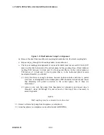
Use of a shaft alignment graph, such as Flowserve Shaft
Alignment Calculator (see SHAFT ALIGNMENT
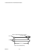
CALCULATOR figure) aids and simplifies the alignment
process. Further information may be obtained through the
Flowserve service department.
11. Rotate both shafts 180 degrees (to the 6 o'clock position) and record indicator reading(s).
12. Repeat steps 10 and 11 to verify accuracy.
13. Set the bracket(s) to the horizontal (9 o'clock) position. Set indicator(s) at "0". Bar sag is not
applicable in the horizontal plane.
14. Rotate both shafts 180 degrees (to the 3 o'clock position) and record indicator reading(s).
15. Repeat steps 13 and 14 to verify accuracy.
16. Measure the distance between dial reading points, and between dial reading point on fixed
unit hub or shaft and each holddown bolt on movable unit (see ALIGNMENT
MEASUREMENT POINTS figure). Record these readings on the graph or by other suitable
means.
17. Follow the directions on the graph sheet or use other suitable means to plot indicator
readings.
NOTE
TIR in either the vertical or horizontal plane shall not
exceed maximum allowable (see OPERATING
SPECIFICATIONS). Readings on opposite sides must be
opposite signs. Total angularity must not exceed 0.001 inch
per 12 inches (0.03 mm per 305 mm).
Figure 3-17 Shaft Alignment Calculator
18. Check holddown bolt positions on the graph or otherwise determine the amount of shims to
be added for the vertical correction, and the movement required for the horizontal correction,
if either exceeds maximums. If maximums are exceeded:
Summary of Contents for IJ
Page 2: ...IJ PUMP INSTALLATION OPERATION MAINTENANCE ...
Page 3: ......
Page 5: ...IJ PUMP OPERATION AND MAINTENANCE MANUAL BO2660 01 iv ...
Page 11: ...IJ PUMP OPERATION AND MAINTENANCE MANUAL BO2660 01 x ...
Page 13: ...IJ PUMP OPERATION AND MAINTENANCE MANUAL BO2660 01 xii ...
Page 17: ...IJ PUMP OPERATION AND MAINTENANCE MANUAL BO2660 01 xvi ...
Page 25: ......
Page 35: ...IJ PUMP OPERATION AND MAINTENANCE MANUAL BO2660 01 2 10 Figure 2 1 Foundation Bolt ...
Page 65: ......
Page 79: ......
Page 83: ......


