Installation Instructions
Page 44
AGT 6000 PVMV-N 12V_24V - Chapter B: Installation Instructions
B.1.3 Fuel System Installation
A fuel filter with water separator is already installed at the generator. Generally fuel intake and
fuel return must be attached with its own fuel intake at the Diesel tank.
If the generator is installed more highly than the tank, the return pipe should be led to the tank up
to the same submergence into the tank as the sucking in line, in order to avoid that after the shut-
off the generator the fuel can run back into the tank, which leads to substantial initial problems
after longer shut-off the generator.
If the return pipe cannot put as immersion tube into the tank, it should be absolutely ensured by a
non-return valve in the sucking in line that the fuel cannot flow back after shut-off the generator.
Basically the Panda is airing out. After the first line-up or after longer downtime the notes "Ventila-
tion of the Fuel System" should be considered.
see “De-aerating the fuel system” on page 70.
The following components must be installed:
1. Fuel pre-filter
2. external fuel pump
3. non-return valve
The external electrical fuel pump is to be installed in the proximity of the tank.
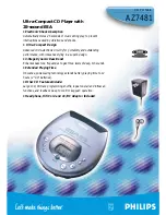
Connection of the fuel system
Fig. B.1.3-1: Fuel connection - Schema
5
2
3
4
1
1. Generator
2. Non return valve
3. External fuel pump
4. External fuel filter
5. Fuel tank
Summary of Contents for AGT 6000 PVMV-N
Page 1: ...Panda AGT 6000 PVMV N Super silent technology 24V 6kW Fischer Panda GmbH ...
Page 6: ......
Page 10: ...8 Socket wrench set Hexagon wrench keys ...
Page 92: ...Generator Failure Page 90 AGT 6000 PVMV N 12V_24V Chapter D Generator Failure ...
Page 100: ...Appendix Page 98 AGT 6000 PVMV N 12V_24V Chapter E Appendix ...
Page 102: ...Page 100 AGT 6000 PVMV N 12V_24V Chapter E E 6 Capsule Measurements ...
Page 106: ...VCS AGT U I Page 104 Chapter A VCS AGT U I VCS AGT UI_eng fm Fischer Panda Datasheet blank ...