Whisper Power GV4 Piccolo, Installation Manual
The Whisper Power GV4 Piccolo, a compact and powerful generator, is an ideal solution for standby power needs. For hassle-free installation and operation, make sure to download the installation manual. It's readily available for free download from our website, ensuring a seamless experience with your new Whisper Power GV4 Piccolo.
Share
Download


Reviews:
No comments
Related manuals for GV4 Piccolo

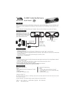
3510
Brand: Wavetek Pages: 6

DBS2300
Brand: DABBSSON Pages: 37
MP301
Brand: CA Pages: 6

Arden
Brand: MagicBox Pages: 20

RAINBOW1000
Brand: Ibiza sound Pages: 28

CPG 4000 INV
Brand: Cross Tools Pages: 68

GD-DM824
Brand: GEARDON Pages: 3

KSB 30i S
Brand: K&S BASIC Pages: 13

JBL PULSE 3
Brand: Harman Pages: 25

GAC3.6HZ
Brand: MULTIQUIP Pages: 82

HW5500 - 5500 Portable Generator
Brand: Honeywell Pages: 1

HW2000i - Portable Inverter Generator
Brand: Honeywell Pages: 1

Generator
Brand: Honeywell Pages: 28

6261
Brand: Honeywell Pages: 32

G0062790
Brand: Honeywell Pages: 36

HW4000 - Portable Generator NOT
Brand: Honeywell Pages: 1

G0070632
Brand: Honeywell Pages: 44

HW4000 - Portable Generator NOT
Brand: Honeywell Pages: 52


