


Operating manual (MC).
CNC 8060
CNC 8065
O
PERATING
IN JO
G MODE
2.
T
ool
cal
ibratio
n
·53·
(R
EF
: 1709)
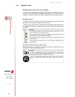
Definition of data
To define the data, place the focus on the relevant data, key in the desired value and press
[ENTER]. To change icons, place the focus on it and press [SPACE].
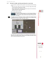
To calibrate the length, radius and wears of a milling tool.
The data shown depends on the calibration option selected with the horizontal softkey menu.
This menu may be used to select the length and/or radius calibration and whether to calculate
their wear or not. If the wears are not calculated, they are reset to zero after the calibration.
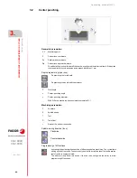
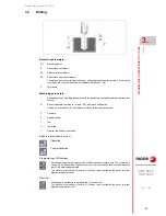
To calibrate the offsets of a milling or lathe tool.
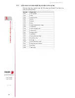
Data
Meaning
T
Tool to be calibrated.
D
Tool offset to be calibrated.
Ds
Safety distance.
F
Probing feedrate.
If not defined, the movements are carried out at the default feedrate, set by the
machine manufacturer.
N
Number of cutters of the tool.
If defined with a ·0· value, the CNC knows the location of a cutter and it will only make
the movement once. The spindle turning speed must be ·0·.
If defined with a value other than ·0·, all cutters will be calibrated. The CNC makes
an initial movement to locate a cutter; then, stops the spindle and makes a precise
measurement of each cutter. It is necessary to define the spindle speed and the Dm
distance.
Dm
Distance the edge of the tool separates from the center of the probe to position the
next cutter.
S
Spindle speed.
Probe side to be touched.
Behavior when exceeding the maximum wear permitted; reject the tool or change it
with another one from the same family.
Lw
Maximum length wear allowed.
Rw
Maximum radius wear allowed.
PRB1MAX
···
PRB2MIN
Probe position.
The values defined here are only taken into account during the calibration cycle; they
do not modify the machine parameter values.
Data
Meaning
T
Tool to be calibrated.
D
Tool offset to be calibrated.
Ds
Safety distance.
F
Probing feedrate.
If not defined, the movements are carried out at the default feedrate, set by the
machine manufacturer.
PRB1MAX
···
PRB2MIN
Probe position.
The values defined here are only taken into account during the calibration cycle; they
do not modify the machine parameter values.
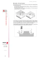
This icon sets the number of axes to calibrate on.
Summary of Contents for CNC 8060
Page 1: ...Ref 1709 8060 8065 CNC Operating manual MC...
Page 8: ...BLANK PAGE 8...
Page 14: ...BLANK PAGE 14...
Page 16: ...BLANK PAGE 16...
Page 18: ...BLANK PAGE 18...
Page 22: ...BLANK PAGE 22...
Page 24: ...BLANK PAGE 24...
Page 26: ...BLANK PAGE 26...
Page 169: ...Operating manual MC CNC 8060 CNC 8065 169 User notes REF 1709...
Page 170: ...Operating manual MC CNC 8060 CNC 8065 170 User notes REF 1709...
Page 171: ...Operating manual MC CNC 8060 CNC 8065 171 User notes REF 1709...


