


Operating manual (MC).
CNC 8060
CNC 8065
2.
O
PERATING
IN JO
G MODE
T
ool
cal
ibratio
n
·50·
(R
EF
: 1709)
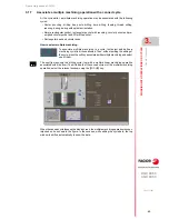
Once a movement has been selected, the window will show a help drawing indicating the
type of calibration to be done.
Definition of data
To define the data, place the focus on the relevant data, key in the desired value and press
[ENTER].
Tool calibration steps
To calibrate the tool, follow these steps:
1
Define the probing distance and feedrate. If the feedrate is not defined, the probing
movement will be made at the feedrate set by the OEM.
2
Select the tool and the offset to be calibrated. After the selection, the CNC shows the
dimensions defined in the tool table for that offset.
To calibrate a tool, it must be the active tool. When selecting a tool and pressing [ENTER],
the CNC only shows the data for that tool. Press [CYCLE START] for the CNC to make
the tool change so it becomes the active tool. See
"Tool calibration"
on page 49.
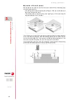
3
Manually approach the tool to the probe until it is placed on the path that will be used
for probing. To calibrate the radius with a cylindrical probe, the path must coincide with
the probe's center point; if not, the radius will be calculated wrong.
4
Calibrate the tool. Select the axis and the probing direction on the softkey menu and press
[START].
The probe moves in parallel to the axis and in the selected direction until touching the
probe. It updates the measured value and resets the wear value to zero. The data is
stored in the tool table.
5
Press [START] again for the CNC to assume the new values of the offset. For the new
values to be assumed, press [START] while the bottom message is displayed; otherwise,
it executes the probing movement again.
Considerations for the offsets and their wear.
It must be borne in mind that the offset of a tool on an axis is the distance between the base
of the tool and its tip (nose). This means that when calculating the offset of a milling tool on
an axis that includes the radius dimension, that radius is included in the offset. The same
is true for the tool length.
When calibrating the offsets of a milling tool, the length value is deleted but not the radius
value.
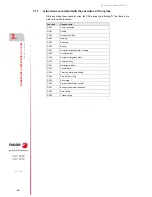
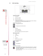
Data
Meaning
PRBMOVE
Maximum probing distance. If the CNC does not receive the probe signal before
reaching moving this probing distance, it stops the axes.
F
Probing feedrate.
T
Tool to be calibrated.
D
Tool offset to be calibrated.
L
Tool length.
Lw
Length wear.
R
Tool radius.
Rw
Radius wear.
Off X
Off Z
Tool offsets on each axis.
Summary of Contents for CNC 8060
Page 1: ...Ref 1709 8060 8065 CNC Operating manual MC...
Page 8: ...BLANK PAGE 8...
Page 14: ...BLANK PAGE 14...
Page 16: ...BLANK PAGE 16...
Page 18: ...BLANK PAGE 18...
Page 22: ...BLANK PAGE 22...
Page 24: ...BLANK PAGE 24...
Page 26: ...BLANK PAGE 26...
Page 169: ...Operating manual MC CNC 8060 CNC 8065 169 User notes REF 1709...
Page 170: ...Operating manual MC CNC 8060 CNC 8065 170 User notes REF 1709...
Page 171: ...Operating manual MC CNC 8060 CNC 8065 171 User notes REF 1709...


