All rights reserved. Reproduction as well as electronic duplication of this guide, complete or in part, requires the written consent of ESERA-
Automation or E-Service GmbH. Errors and technical modification subject to change.
©
ESERA-Automation, E-Service GmbH 2019
www.esera.de
Programming Manual Controller-Gateway-Station V1.0 R1.1
Page 9 of 77
4.
Introduction
1-Wire Controller / 1-Wire Gateway
In some parts of the document, the term “1-Wire Controller” is used to represent 1-Wire Controller,
1-Wire Gateway and the 1-Wire function of the ESERA station. This keeps the document clear and legible.
For reasons of maintainability, we have compiled the following command list uniformly for all units
of the 1-Wire Controller 1 and 1-Wire Controller 2. We have added a note to those parts that are
specifically intended for the 1-Wire Controller 2.
The offered device software (firmware) can be used for all 1-Wire Controller 1 and 1-Wire Controller 2. The
device software is designed in such a way that commands, that are not intended for this device, are
deactivated.
The 1-Wire Controller / 1-Wire Gateway is a self-sufficient working subsystem among a 1-Wire network and a
computer, PLC control or web application respectively cloud services. It reads all connected 1-Wire devices in an
extremely fast time-cycle of 1-2 seconds. This means that device data is available in a very short time frame.
Status changes of input signals, e.g. on digital input modules, are thus quickly detected.
Exclusively for 1-Wire Controller 2 / 1-Wire Gateway 20:
The 1-Wire Controller 2 and 1-Wire Gateway 20 also provide 5 binary outputs with 8A/5A relays, 4 binary inputs
10-30VDC and an isolated 0-10V output.
In addition, the 1-Wire Controller 2 and 1-Wire Gateway 20 provides room for an optional expansion module, e.g.
for analog input signals or S0 counters.
4.1.
Integration of new 1-Wire devices
If a new 1-Wire device is integrated into the 1-Wire network, it will be automatically detected after a few seconds
and added to the internal device list, where it is read out and output.
4.2.
Cyclic data output and formatting
The 1-Wire Controller / 1-Wire Gateway outputs the data, read by the devices via the data interface in a prepared
and cyclically formatted form.
Further knowledge of 1-Wire protocols is not necessary on the part of the end-user, as the entire 1-Wire
communication is handled by the 1-Wire Controller / 1-Wire Gateway.
4.3.
Number of 1-Wire devices and types
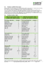
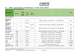
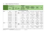
Up to 30 1-Wire devices of type DS1820, DS18S20, DS18B20, DS2405, DS2408, DS2413, DS2423, DS2438 and
DS2450 are supported, that can be read and controlled,.
4.4.
iButton access keys or DS2401 serial numbers
Also iButton access keys of type DS2401, DS1990A and DS1963 can be used.
Other modules are available on request.
iButton keys or DS2401 serial number modules can be easily connected to the 1-Wire Controller / DS1963.
1-Wire Gateway can be trained. It is only necessary to hold the iButton key on the iButton reader for 10 seconds.
Then the iButton is already present in the 1-Wire Controller / 1-Wire Gateway as an OWD. The iButton key can
now be used. Permanent storage requires the "SET,OWB,SAVE" command or the "SAVE ALL OWD
PERMANENT" button has to be pressed in Config-Tool 3.
4.5.
1-Wire operating mode
Modules can be connected in normal mode (3-wire system) and in parasitic mode (2-wire system). A mixed
operating mode is also possible.
4.6.
Power supply 1-Wire network
The 1-Wire Controller 1, 1-Wire Gateway 10 or 1-Wire Gateway 11 provides a 5V voltage for the 1-Wire network
with up to approx. 150mA current.


