All rights reserved. Reproduction as well as electronic duplication of this guide, complete or in part, requires the written consent of ESERA-
Automation or E-Service GmbH. Errors and technical modification subject to change.
©
ESERA-Automation, E-Service GmbH 2019
www.esera.de
Programming Manual Controller-Gateway-Station V1.0 R1.1
Page 41 of 77
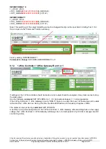
Example:
1_LST2|18:49:50
LST|1_OWD1|2863DD51040000FF|DS18B20
LST|1_OWD2|26D9DA88010000BE|DS2438
LST|1_OWD3|FFFFFFFFFFFFFFFF|none
…
LST|1_OWD30|FFFFFFFFFFFFFFFF|none
11.
Data output of system-internal inputs / outputs
Controller 2 / Gateway 20
The following functions are available only for the 1-Wire Controller 2 / 1-Wire Gateway 20.
For the system-internal inputs and outputs a cyclic data output takes place, identical to the 1-Wire devices /
modules.
In addition, there is an event-controlled data output as soon as the status of a digital input has changed. The
formatting of event-controlled data output is the same as that of cyclic data output.
In order to be able to distinguish the data output of the system-internal inputs and outputs from the data output of
the 1-Wire devices or sensors and actuators, the internal data records are designated as "SYS".
11.1.
Digital inputs
Data output for the digital / binary inputs is in decimal and binary data format. All four inputs are displayed with a
numerical value in the range of 0-15. Each input has a value that is added up. Input 1 active = 1, input 2 active =
2, input 3 active = 4, input 4 active = 8.
An input is active if a DC voltage in the range of 10-30VDC is available.
Data output:
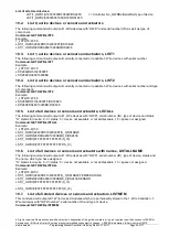
1_SYS1_1|0
=> Controller No._ System No._DataRecord| InputValue (DEZ)
1_SYS1_2|00000000
=> Controller No._ System No._DataRecord| InputValue (BIN)
11.2.
Digital output
The status of the digital / binary relay outputs is in decimal and binary data format.
All 5 outputs are displayed with a numerical value in the range 0-31. Each output has a value that is added up.
Output 1 active = 1, output 2 active = 2, output 3 active = 4, output 4 active = 8 and output 5 active = 16.
An output is active if a relay has been switched on or switched to output 5.
Data output:
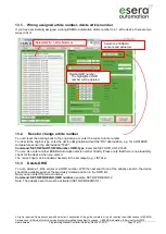
1_SYS2_1|0
=> Controller No._ System No._DataRecord| OutputImage (DEZ)
1_SYS2_2|00000000
=> Controller No._ System No._DataRecord| OutputImage (BIN)
11.3.
Analog Output
The current analog value of the 0-10V output is stored as an integer value corresponding to 0-10V with
2 decimal places. This means that a value in the number range from 0 to 1000 is output. This corresponds to an
analog value of 0 - 10.00 volts.
Data output:
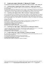
1_SYS3|850
=> Controller No._ System No.| OutputValue, e.g. 850 for 8,5V


