All rights reserved. Reproduction as well as electronic duplication of this guide, complete or in part, requires the written consent of ESERA-
Automation or E-Service GmbH. Errors and technical modification subject to change.
©
ESERA-Automation, E-Service GmbH 2019
www.esera.de
Programming Manual Controller-Gateway-Station V1.0 R1.1
Page 35 of 77
9.1.6.
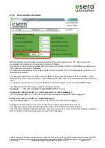
Keep Alive Receive Alarm
With this function, the entire data transmission path and the control system, PLC, PC, can be monitored
backwards and an alarm can be triggered in the event of failure.
An output of a 1-Wire switching module with the components DS2405, DS2413 or DS2408 can be assigned as
alarm output for missing KAL messages.
In addition, an internal relay can be assigned to the 1-Wire Controller 2 or 1-Wire Gateway 20 in addition to a 1-
Wire switching module.
The assigned output can be used as a normal output in regular operation (without 1-Wire Controller / 1-Wire
Gateway alarm). The 1-Wire Controller / 1-Wire Gateway uses this output for its own purposes in the event of an
alarm.
To assign an internal relay to a 1-Wire Controller 2 or 1-Wire Gateway 20, enter "0" for the OWD number.
The assignment of the "KAL alarm output" is performed with the
Command
:
SET,SYS,CALARM,OWD-NUMBER,OUTPUT,VALUE
Example for 1-Wire Controller 1 or 1-Wire Gateway 10 or 1-Wire Gateway 11
:
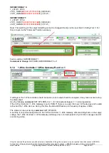
SET,SYS,KALALARM,2,3,1 => OWD 2, binary output 3 becomes 1 when KAL alarm is triggered.
Example for 1-Wire Controller 2 or 1-Wire Gateway 20
:
SET,SYS,KALALARM,0,1,1 => Internal relay 1 becomes 1 when KAL alarm is triggered.
Settings for the KAL alarm can be set via Config-Tool 3 settings (from Config-Tool 3 V1.5).
The assigned output remains permanently stored in the 1-Wire Controller or 1-Wire Gateway.
This "KAL Alarm Output" is activated when the max. KAL receive time is exceeded and remains active until the 1-
Wire Controller or 1-Wire Gateway again receives "KAL" messages.


