All rights reserved. Reproduction as well as electronic duplication of this guide, complete or in part, requires the written consent of ESERA-Automation or E-Service GmbH. Errors and technical modification subject
to change.
©
ESERA-Automation, E-Service GmbH 2019
www.esera.de
Programming Manual Controller-Gateway-Station V1.0 R1.1
Page 15 of 77
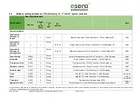
5.5.
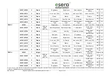
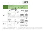
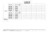
Modbus reading addresses, 1-Wire Gateway 10, 11 and 20, system variables
Description
Reading addresses
Note
Address
Number
of
words
(16Bit)
Type
of
data
Bit
address
System variables
Controller 2,
Gateway 20
inputs
1
1
Word
Status binary input 1-Wire Controller 2 / 1-Wire Gateway 20
HHLL
Controller 2,
Gateway 20
outputs
2
1
Word
32 to 36
Status binary output 1-Wire Controller 2 / 1-Wire Gateway 20
HHLL
Controller 2,
Gateway 20
analog output
3
1
Word
16 to 19
Status analog output 1-Wire Controller 2 / 1-Wire Gateway 20
HHLL
Controller No.
60000
1
Word
Output of assigned numbers 1-Wire Controller / 1-Wire Gateway
HHLL
Article-No.
60001
1
Word
Article number 1-Wire Controller / 1-Wire Gateway
HHLL
Firmware version
61000
4
String
Firmware version 1-Wire Controller / 1-Wire Gateway
HHLL
Hardware version
61010
3
String
Hardware version 1-Wire Controller / 1-Wire Gateway
HHLL
Serial number
61020
9
String
Serial number 1-Wire Controller / 1-Wire Gateway
HHLL
Time
61030
4
String
time (RTC) 1-Wire Controller / 1-Wire Gateway
hh:mm:ss
Date
61035
4
String
date (RTC) 1-Wire Controller / 1-Wire Gateway
tt.mm.jj
Time, date
61030
9
String
Combination of time and date (RTC)
hh:mm:ss
tt.mm.jj
Number of OWD
61039
1
Word
Output number of 1-Wire (OWD) sensors or actuators are stored
HHLL


