


Setup & Operation 5. Motion Range
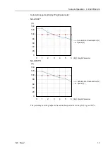
N6 Rev.2
65
5. Motion Range
WARNING
■
When limiting the motion range for safety, be sure to set by the pulse range.
Failure to do so may cause serious safety problems.
The motion range is preset at the factory as describes in the
Setup & Operation 2.4
Standard Motion Range
. This is the maximum motion range of the Manipulator.
Motion range is set by the following two methods:
1. Setting by pulse range (for all arms)
2. Setting the Cartesian (rectangular) range in the X, Y coordinate system of the
Manipulator
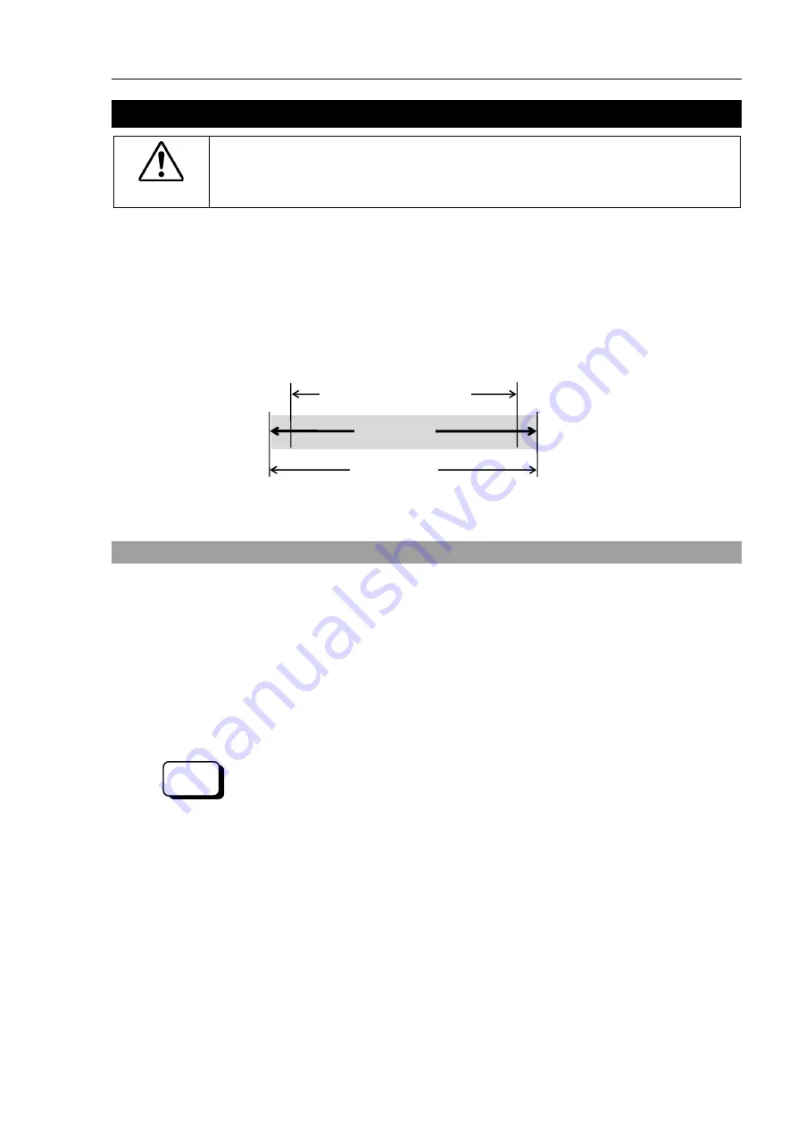
Rectangular Range Setting
Pulse Range
Motion Range
When the motion range is limited due to layout efficiency or safety, follow the descriptions
in
5.1
through
5.3
to set the range.
5.1 Motion Range Setting by Pulse Range (for Each Joint)
Pulses are the basic unit of Manipulator motion. The motion range of the Manipulator is
controlled by the pulse range (the lower limit and the upper limit) of each axis.
Pulse values are read from the encoder output of the servo motor.
The pulse range should be set within the maximum motion range.
Once the Manipulator receives an operating command, it checks whether the target
position specified by the command is within the pulse range before operating. If the
target position is out of the set pulse range, an error occurs and the Manipulator does not
move.
EPSON
RC+
The pulse range can be set in [Tools]-[Robot manager]-[Range] panel.
You may also execute the Range command from the [Command Window].
NOTE
Summary of Contents for N6 Series
Page 1: ...Rev 2 EM187R3735F 6 Axis Robots N6 series MANIPULATOR MANUAL ...
Page 2: ...Manipulator manual N6 series Rev 2 ...
Page 8: ...vi N6 Rev 2 ...
Page 14: ......
Page 27: ...Setup Operation 1 Safety N6 Rev 2 15 N6 A850 R C A D F G F E H G F B G F G F F F N6 A850 BR F ...
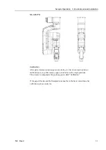
Page 34: ...Setup Operation 2 Specifications 22 N6 Rev 2 N6 A850 BR Cable direction Upward ...
Page 52: ...Setup Operation 3 Environment and Installation 40 N6 Rev 2 N6 A850 R Maximum motion range 802 ...
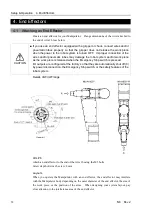
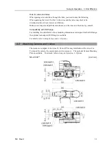
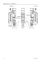
Page 66: ...Setup Operation 4 End Effectors 54 N6 Rev 2 N6 A850 R Unit mm ...
Page 104: ......
Page 274: ...Maintenance 4 Cable 262 N6 Rev 2 4 7 1 Signal Power cable ...
Page 275: ...Maintenance 4 Cable N6 Rev 2 263 ...
Page 276: ...Maintenance 4 Cable 264 N6 Rev 2 4 7 2 User Cable ...


