


Maintenance 3. Covers
N6 Rev.2
119
Installation
(1) Make sure that the base cover is removed and the Arm #1 is at the origin position.
For procedures to remove the base cover, refer to
Maintenance 3.1 Base Cover.
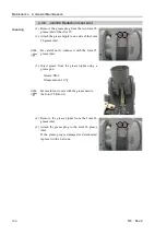
(2) Set the Joint #1 cover to the installation
position and move the Arm #1 to a position
where you can install the cover easily.
Joint #1 cover
When moving the arm, be careful not to get the cover caught on the manipulator.
If you move the cover while the cover is got caught on the Manipulator, the cover may
get broken.
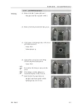
(3) Fix the Joint #1 cover with the screws.
Cross recessed binding head machine screw:
2-M4×8
Tightening torque: 0.45
±
0.05 N·m
The cover may get broken if it is fastened too tight.
Be careful not to exceed the above tightening
torque.
(4) Install the Arm #1 outside cover.
Hexagon socket head cap bolts:
8-M5
×
20 (with plain washer)
Tightening torque: 8.0
±
0.4 N·m
(5) Install the base cover.
For more details, refer to
Maintenance 3.1 Base Cover
.
NOTE
NOTE
Summary of Contents for N6 Series
Page 1: ...Rev 2 EM187R3735F 6 Axis Robots N6 series MANIPULATOR MANUAL ...
Page 2: ...Manipulator manual N6 series Rev 2 ...
Page 8: ...vi N6 Rev 2 ...
Page 14: ......
Page 27: ...Setup Operation 1 Safety N6 Rev 2 15 N6 A850 R C A D F G F E H G F B G F G F F F N6 A850 BR F ...
Page 34: ...Setup Operation 2 Specifications 22 N6 Rev 2 N6 A850 BR Cable direction Upward ...
Page 52: ...Setup Operation 3 Environment and Installation 40 N6 Rev 2 N6 A850 R Maximum motion range 802 ...
Page 66: ...Setup Operation 4 End Effectors 54 N6 Rev 2 N6 A850 R Unit mm ...
Page 104: ......
Page 274: ...Maintenance 4 Cable 262 N6 Rev 2 4 7 1 Signal Power cable ...
Page 275: ...Maintenance 4 Cable N6 Rev 2 263 ...
Page 276: ...Maintenance 4 Cable 264 N6 Rev 2 4 7 2 User Cable ...


