


Maintenance 7. Boards
336
N6 Rev.2
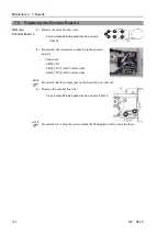
Installation
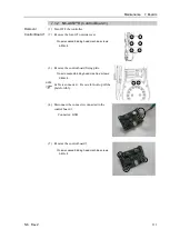
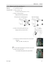
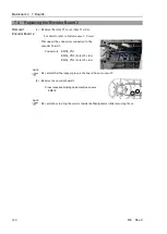
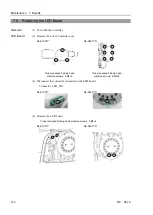
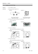
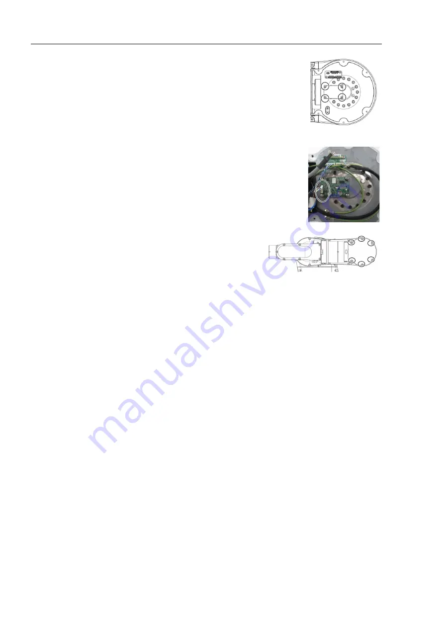
Control Board 2
(1) Install the control board #2 to the Arm #3.
Cross recessed binding head machine screws: 4-M3×6
Tightening torque: 0.45
±
0.05 N·m
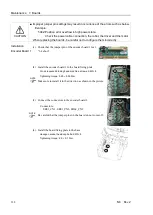
Be careful not to drop the screws inside the Manipulator while removing them.
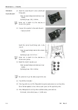
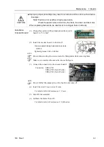
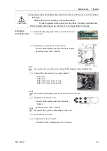
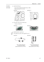
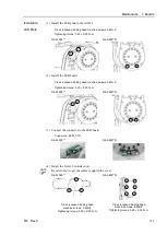
(2) Connect the connector to the control board 2.
Connector: GS02
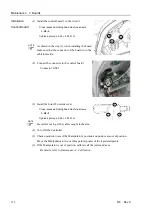
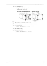
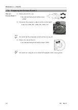
(3) Install the Arm #3 cover.
Cross recessed binding head machine screws:
6-M4×8
Tightening torque: 0.45
±
0.05 N·m
Be careful not to get the cables caught in the cover.
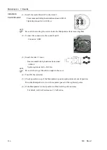
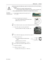
(4) Turn ON the controller.
(5) Check operation to see if the Manipulator's position and posture are out of position.
Move the Manipulator to two or three points (poses) of the registered points.
(6) If the Manipulator is out of position, calibrate all the joints and axes.
For details, refer to
Maintenance 8. Calibration
.
NOTE
NOTE
Summary of Contents for N6 Series
Page 1: ...Rev 2 EM187R3735F 6 Axis Robots N6 series MANIPULATOR MANUAL ...
Page 2: ...Manipulator manual N6 series Rev 2 ...
Page 8: ...vi N6 Rev 2 ...
Page 14: ......
Page 27: ...Setup Operation 1 Safety N6 Rev 2 15 N6 A850 R C A D F G F E H G F B G F G F F F N6 A850 BR F ...
Page 34: ...Setup Operation 2 Specifications 22 N6 Rev 2 N6 A850 BR Cable direction Upward ...
Page 52: ...Setup Operation 3 Environment and Installation 40 N6 Rev 2 N6 A850 R Maximum motion range 802 ...
Page 66: ...Setup Operation 4 End Effectors 54 N6 Rev 2 N6 A850 R Unit mm ...
Page 104: ......
Page 274: ...Maintenance 4 Cable 262 N6 Rev 2 4 7 1 Signal Power cable ...
Page 275: ...Maintenance 4 Cable N6 Rev 2 263 ...
Page 276: ...Maintenance 4 Cable 264 N6 Rev 2 4 7 2 User Cable ...


