Chapter 4 Operation Procedures 33
EV1000 Series General Purpose Variable Speed Drive User Manual
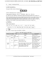
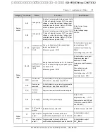
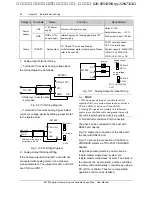
Refer to the figure below. Reference Frequency is decided by the BIT2 of the one’s place of F8.01. If
BIT2=1, it means the parameter will be displayed. For those parameters you don’t want to display, you
may set the corresponding bit at Zero. Therefore, it turns out to be “0100”, after converting to HEX value,
it is 4. So , you should set the one’s place at 4.
2. Set Ten’s place
Similarly, set the corresponding bit at “1” for those parameters you want to display, you will get “1111”, i.e.
“F”.
3. Set Hundred’s and Thousand’s place
Since no parameters related to hundred’s and thousand’s place are required to display, so they are set at
zero.
From the above, F8.01 is set at 00F4.
Thousand
Hundred Ten one
BIT0: output freq. (before compensation)
BIT1: output freq.(after comensation)
BIT2: set freq.
BIT3: output current (A)
BIT0
:
actual speed (rpm)
BIT1
:
set speed
(rpm)
BIT2
:
actual line speed (m/s)
BIT3
:
set line speed (m/s)
BIT0
:
output power
BIT1
:
output torque (%)
BIT2
:
reserved
BIT3
:
reserved
BIT0
:
reserved
BIT1
:
reserved
BIT2
:
reserved
BIT3
:
reserved
Under menu level 3, if no digit of a parameter is blinking, it means it is unchangeable. The possible
reasons are:
The parameter is unchangeable, such as measured parameters, operation log, etc;
The parameter can be changed at stop state only;
The parameter is protected. When FP.01=1 or 2, the parameter is protected. You should set FP.01=0 to
allow the modification.
4.2.5 Speed Setting
If the initial state is actual speed, set speed, actual line speed or set line speed, you may press
▲
or
▼
key to change the set speed and set line speed real-time. If you want to change the reference setting,
press
key to shift the LED display to frequency then change it.
艾默生变频器、艾默生CT高级授权代理商--广州盟雄 020-85543394 qq:2294731312


