


42 Chapter 5 Parameters
EV1000 Series General Purpose Variable Speed Drive User Manual
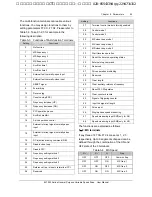
Output Freq.
Initial Freq.of braking
Output
volt
(
RMS value
)
Braking
Energy
Braking time
Operating
command
Waiting time
Fig. 5-15 DeceleDC braking Process
F2.13 Dynamic braking
Range: 0, 1
【
0
】
0: disabled
1: enabled
Note:
Please set this parameter properly according to your
needs, otherwise, the control performance will be
suffered.
F2.14 Ration of braking
time to total operating time
Range: 0.0
~
100.0
%【
2.0
%】
The max. continuous dynamic braking time is
calculated with 100s as a cycle.
Note
:
The resistance and power of the braking resistor
should be considered.
5.4 Auxiliary Operating
Parameters (F3)
F3.00 Anti-reverse setting Range: 0, 1
【
0
】
0: reverse allowed
1: reverse not allowed
Note
:
The function is effective to all command giving
method, including keypad, terminal and serial port.
F3.01 FWD/REV
transition time
Range: 0~3600s
【
0.0s
】
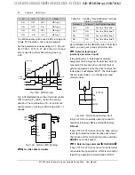
It refers to the time period when the drive’s
rotation changes from FWD to REV or REV to
FWD, see Fig. 5-16 as t
1
.
Time
t
1
Output
frequency
Fig. 5-16 Transition time from FWD to REV
F3.02~F3.04
RESERVED
F3.05
Auto energy saving Range: 0, 1
【
0
】
0: disabled
1: enabled
The drive can detect load current and adjust
voltage accordingly to save energy.
Note
:
This function is preferable to the load such as fan and
pump.
F3.06 AVR Function
Range: 0, 1, 2
【
2
】
0: disabled
1: always enabled
2: disabled during decelerating
AVR: auto voltage adjustment. This function can
keep constant output voltage when the input
voltage deviates from rated value. Therefore, the
function should be enabled all the time especially
when the input voltage is higher than the rated
value.
If AVR is disabled during deceleration, the Dec
time is shorter but the current is higher, otherwise,
the motor decelerates smoothly with lower current,
but the Dec time is longer.
艾默生变频器、艾默生CT高级授权代理商--广州盟雄 020-85543394 qq:2294731312


