


Chapter 5 Parameters 37
EV1000 Series General Purpose Variable Speed Drive User Manual
Note:
1. Wrong parameter setting can cause overheating of
the motor or triggers the over-current protection of the
drive.
2. Refer to F0.21 for definition of fz.
3. When using synchron motor, you should select
manual torque boost, and adjust V/F curve according
to the motor parameters and application.
F0.10 Acc time 1 Range: 0.1
~
3600s
(
min
)【
6.0s
】
F0.11 Dec time 1 Range: 0.1
~
3600s
(
min
)【
6.0s
】
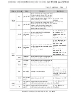
output
frequency
t
1
f
max
t
2
time
Fig. 5-4 Acc/Dec time definition
Acc time is the time taken for the motor to
accelerate from 0 Hz to the maximum frequency
(as set in F0.05), see t
1
in Fig. 5-4.
Dec time is the time taken for the motor to
decelerate from maximum frequency (F0.05) to 0
Hz, see t
2
in Fig. 5-4.
EV1000 has four pair of acc/dec time. Here we
only introduce acc/dec 1. Please find acc/dec
time 2~4 in section 5.4: F3.17
~
F3.22.
Hint
:
The unit of acc/dec 1~4 can be selected by F9.09, the
options are: minute, second. The default is second.
F0.12 Upper limit of
freq.
Range: upper limet
~
max. output
frequency
【
50.00Hz
】
F0.13 Lower limit of
frequency
Range: 0
~
upper limet of frequency
【
0.00Hz
】
Please refer f
H
and f
L
in Fig. 5-2.
Note
:
It is possible for the actual output frequency to
fluctuate within
±
2.5Hz in the bus-voltage control
process.
F0.14 V/F curve setting
Range: 0
~
3
【
0
】
F0.15 V/F freq. F3
Range: F0.17
~
F0.06
【
0.00Hz
】
F0.16 V/F voltage V3
Range: F0.18
~
100.0
%【
0.0
%】
F0.17 V/F freq. F2
Range: F0.19
~
F0.15
【
0.00Hz
】
F0.18 V/F voltage V2
Range: F0.20
~
F0.16
【
0.0
%】
F0.19 V/F freq. F1
Range: 0
~
F0.17
【
0.00Hz
】
F0.20 V/F voltage V1
Range: 0
~
F0.18
【
0.0
%】
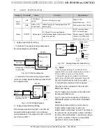
This group of parameters defines the V/F setting
modes so as to satisfy the requirements of
different loads. Three fixed curves and one
user-defined curve can be selected according to
the setting of F0.14.
If F0.14 is set to 1, a 2-order curve is selected, as
shown in Fig. 5-5 as curve 1;
If F0.14 is set to 2, a 1.7-order curve is selected,
as shown in Fig. 5-5 as curve 2;
If F0.14 is set to 3, a 1.2-order curve is selected,
as shown in Fig. 5-5 as curve 3;
The above V/F curves are suitable for the
variable-torque loads such as fan & pumps. The
user can select the curves according to the actual
load so as to achieve the best energy-saving
effects.
艾默生变频器、艾默生CT高级授权代理商--广州盟雄 020-85543394 qq:2294731312


