Chapter 5 Parameters 69
EV1000 Series General Purpose Variable Speed Drive User Manual
serial port to change auxiliary frequency.
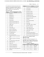
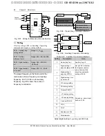
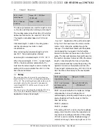
If VCI-5 or CCI-5 is selected, take 5V input as the
point corresponding to zero frequency, 0~5V input
corresponds to negative output, 5~10V input
corresponds to positive output. See Fig.5-60.
Fig. 5-60 Frequency Setting Via VCI-5 or CCI-5
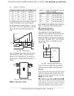
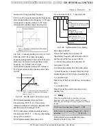
If PULSE-0.5×F1.03 is taken as auxiliary
frequency setting method, one half of F1.03 (max.
pulse freq.) as the point corresponding to zero
frequency, 0~0.5 times of F1.03 input
corresponds to negative output, 0.5~1 times of
F1.03 input corresponds to positive output. See
Fig.5-61.
0
F1.03 Pulse
Auxiliary frequency
0.5 fmax
-0.5 fmax
Pmid——1/2 *Max input pulse frequency (F1.03)
fmax——frequency corresponds to Max analog
value (F1.07 or F1.11)
Pmid
Fig. 5-61 PULSE-0.5×F1.03 As Freq. Input
F9.02: Analog auxiliary reference factor
It is valid when F9.01=4~12. The auxiliary
reference undergoes F9.02 gain calculation first,
and then output according to F1.00.
F9.03: initial value of digital auxiliary reference
It is valid when F9.01=1
~
3. It is the initial setting
of any of the 3 method.
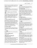
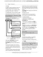
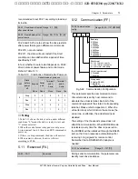
F9.04: digital auxiliary reference control
It is valid when F9.01=1
~
3. See Fig. 5-62.
Thou.
Ten One
Save
0: Save ref. Freq. upon power outage
1: Not save ref. Freq. upon power
outage
Stopping freq.
0: Hold ref. Freq. at stop
1: Clear ref. Freq. at stop
Sign of auxi. ref. Freq.
0: +, main ref+ auxi. ref. Freq.
1:
-
, main ref
-
auxi. ref. Freq.
Reserved
Hun.
Fig. 5-62 Digital Auxiliary Freq. Setting
One’s place of F9.04
0: save the auxiliary freq. at power off
The auxiliary frequency will be saved in F9.03,
and the sign of the freq. saved in F9.04.
1: not save the auxiliary freq. at power off
Ten’s place of F9.04
0: maintain the auxiliary freq. if the drive stops
1: preset frequency is cleared if the drive stops
Hundred’s place of F9.04: sign of auxiliary freq.
0: (+) positive sign.
Preset freq. is the sum of main freq. and auxiliary
freq.
1: (+) negative sign
Preset freq. is the result of main freq. minus
auxiliary freq.
Note
:
When the inputting mode of auxiliary reference
frequency is the same with that of main reference
frequency, the auxiliary reference frequency setting is
invalid.
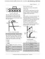
F9.05 Preset freq.adjust mode Range: 0
~
2
【0】
F9.06 Factor for calculating
preset freq.
Range: 0.0
%~
200.0
%
【
100.0
%】
F9.05 defines how to calculate the preset
frequency. Refer to Fig. 5-57.
艾默生变频器、艾默生CT高级授权代理商--广州盟雄 020-85543394 qq:2294731312

