


40 Chapter 5 Parameters
EV1000 Series General Purpose Variable Speed Drive User Manual
Note:
1. Start mode 1 applies to small-inertia motor when
the drive stops, the motor is still rotating. For
large-inertia load, do not restart until the motor stops.
2. When driving synchronized motor, it is
recommended to use start mode 0.
F2.01 Start frequency
Range: 0.20
~
60.00Hz
【
0.50Hz
】
F2.02 Start frequency
hold time
Range: 0.0
~
10.0s
【
0.0s
】
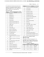
Start frequency refers the frequency at which the
drive starts, as shown in Fig. 5-11 as f
S
; start
frequency hold time refers the time within which
the drive runs at start frequency during startup, as
shown in Fig. 5-11 as t
1
:
t
1
Time
f
s
f
max
Freq. (Hz)
Fig. 5-11 Relation of Start Freq. and Start Time
Note:
The start frequency is not limited by lower limit of the
frequency.
F2.03 DC brake current
at startup
Range: depending on model
【
0.0
%】
F2.04 DC brake time at
startup
Range: depending on model
【
0.0s
】
F2.03 and F2.04 are valid only when you set
F2.00=1, that is, braking before starting. See Fig.
5-12.
DC brake current at startup is determined by drive
model, for G type: 0~150% of drive’s rated current
(max. current among the 3 phases), P type:
0~130% of drive’s rated current (max. current
among the 3 phases).
If the brake time at startup is set at 0.0s, no brake
process.
Output
frequency
Output
voltage
(
effective
value
)
Braking
energy
DC injection
braking time
Running
command
Time
Time
Fig. 5-12 Start Mode 1
F2.05 Acc/Dec mode
Range: 0, 1, 2
【
0
】
F2.05=0: linear Acc/Dec
The output frequency increase or decrease
according to a fixed slope, see Fig. 5-13.
F2.05=1: S curve Acc/Dec
The output frequency increase or decrease
according to S curve, see Fig. 5-14.
F2.05=2: automatic Acc/Dec
The output current of the drive is limited below the
current limiting level according to the load, see
FL.07. The Acc/Dec is done smoothly.
Frequency
Time
f
max
t
1
t
2
Fig. 5-13 Linear Acc/Dec Curve
艾默生变频器、艾默生CT高级授权代理商--广州盟雄 020-85543394 qq:2294731312


