


46 Chapter 5 Parameters
EV1000 Series General Purpose Variable Speed Drive User Manual
RUN
command
f
1
f
2
f
3
f
4
f
5
f
6
f
7
T
1
T
2
T
3
T
4
T
5
T
6
T
7
a
1
a
2
a
3
d
3
a
4
d
5
a
5
a
6
d
7
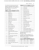
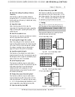
Fig. 5-23 Maintain Last Stage After Single Cycle
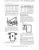
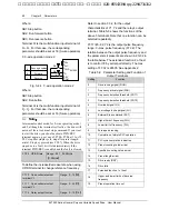
3: Continuous cycle.
The drive continue running cycle after cycle until
Stop command is received.
RUN
command
STOP
command
f
1
f
2
f
3
f
4
f
5
f
6
f
7
T
1
PLC
operation
f
1
f
2
f
3
f
4
f
5
f
6
f
7
f
1
d
1
d
1
d
2
First cycle
Second cycle
...
T
2
T
3
T
4
T
6
T
5
T
7
T
1
T
2
T
3
T
4
T
6
T
5
T
7
T
1
Fig. 5-24 PLC Continuous Cycle
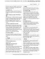
Ten’s place of F4.00: Restart mode after PLC
interruption
0: start from the first stage
The drive restarts from the first stage of PLC after
interrupts, such as Stop command, fault or
poweroff.
1: continue from the stage frequency where the
drive stops
When the drive stops caused by Stop command
or fault, it can record the time that it has
undergone in the current stage. After receiving
Run command, it will run at the preset frequency
of the stage for the remaining time of the stage,
as Fig. 5-25 shows.
Stopping signal
...
Stage 1
f
1
a
1
Output freq.Hz
Remnant time of
stage 2
f
2
d
2
a
2
...
f
3
a
3
a
1
: Acc time of stage 1
2
: Acc time of stage 2
a
3
: Acc time of stage 3
2
: Dec time of stage 2
f
1
: Freq. of stage 1
2
: Freq. of stage 2
f
3
: Freq. of stage 3
Operating
time of
stage 2
Time
a
d
f
Fig. 5-25 PLC Restart Mode 1
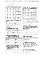
2: Start from the frequency where it stops
When the drive stops caused by Stop command
or fault, it can record both the time it has
undergone in the current stage and the very
frequency when the drive stops. It will pick up the
recorded frequency and run for the remaining
time of the stage. See Fig. 5-26.
a
1
: Acc time of stage 1
2
: Acc time of stage 2
a
3
: Acc time of stage 3
2
: Dec time of stage 2
f
1
: Freq. of stage 1
2
: Freq. of stage 2
f
3
: Freq. of stage 3
Stopping signal
...
Stage 1
f
1
a
1
Operating
time of
stage 2
Remnant time of
stage 2
Output freq. Hz
Time
f
2
d
2
a
2
...
f
3
a
3
d
2
a
a
f
Fig. 5-26 PLC Start Mode 2
Note:
The difference between PLC start mode 1 and mode 2
is that in mode 2, the drive can record the operating
frequency when the drive stops and continue to
operate at the recorded frequency after restart.
Hundred’s place of F4.00: Save PLC state after
poweroff
0: not save
The PLC state will not be saved when poweroff,
and the drive will start from the first stage after
powerup.
1: save
The PLC state, including the stage, frequency, run
艾默生变频器、艾默生CT高级授权代理商--广州盟雄 020-85543394 qq:2294731312


