Safety
Information
Product
Information
Mechanical
Installation
Electrical
Installation
Getting
Started
Basic
parameters
Running
the motor
Optimization
SMARTCARD
operation
PC tools
Advanced
parameters
Technical
Data
Diagnostics
UL Listing
Information
Affinity User Guide
77
Issue Number: 5 www.controltechniques.com
Minimum resistances and power ratings
Table 4-12 Minimum resistance values and peak power rating for
the braking resistor at 40°C (104°F)
* Resistor tolerance: ±10%
** The minimum resistance value specified is for a stand-alone drive
only. If the drive is part of a common DC bus system a different value
must be used. Contact the supplier of the drive for more information.
For high-inertia loads or under continuous braking, the
continuous
power
dissipated in the braking resistor may be as high as the power rating of
the drive. The total
energy
dissipated in the braking resistor is dependent
on the amount of energy to be extracted from the load.
The instantaneous power rating refers to the short-term maximum power
dissipated during the
on
intervals of the pulse width modulated braking
control cycle. The braking resistor must be able to withstand this
dissipation for short intervals (milliseconds). Higher resistance values
require proportionately lower instantaneous power ratings.
In most applications, braking occurs only occasionally. This allows the
continuous power rating of the braking resistor to be much lower than
the power rating of the drive. It is essential, though, that the
instantaneous power rating and energy rating of the braking resistor are
sufficient for the most extreme braking duty that is likely to be
encountered.
Optimization of the braking resistor requires a careful consideration of
the braking duty.
Select a value of resistance for the braking resistor that is not less than
the specified minimum resistance. Larger resistance values may give a
cost saving, as well as a safety benefit in the event of a fault in the
braking system. Braking capability will then be reduced, which could
cause the drive to trip during braking if the value chosen is too large.
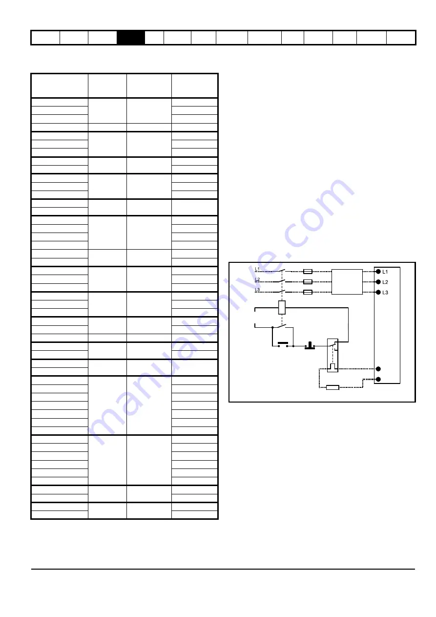
Thermal protection circuit for the braking resistor
The thermal protection circuit must disconnect the AC supply from the
drive if the resistor becomes overloaded due to a fault. Figure 4-14
shows a typical circuit arrangement.
Figure 4-14 Typical protection circuit for a braking resistor
See Figure 4-1 on page 66, Figure 4-2 and Figure 4-3 on page 67, and
Figure 4-4 on page 68 for the location of the +DC and braking resistor
connections.
Model
Minimum
resistance*
Ω
Instantaneous
power rating
kW
Average power
for 60s
kW
BA1201
43
3.5
1.5
BA1202
2.2
BA1203
3.0
BA1204
29
5.3
4.4
BA2201
18
8.9
6.0
BA2202
8.0
BA2203
8.9
BA3201
5.0
30.3
13.1
BA3202
19.3
BA4201**
5.0
30.3
22.5
BA4202**
27.8
BA4203**
30.3
BA5201
3.5
53
43.5
BA5202
BA1401
74
8.3
1.5
BA1402
2.2
BA1403
3.0
BA1404
4.4
BA1405
58
10.6
6.0
BA1406
8.0
BA2401
19
33.1
9.6
BA2402
13.1
BA2403
19.3
BA3401
18
35.5
22.5
BA3402
27.8
BA3403
33.0
BA4401**
11
55.3
45.0
BA4402**
53.0
BA4403**
9
67.6
67.5
BA5401**
7
86.9
82.5
BA5402**
86.9
BA6401
5
122
122
BA6402
BA3501
18
50.7
4.4
BA3502
6.0
BA3503
8.0
BA3504
9.6
BA3505
13.1
BA3506
19.3
BA3507
22.5
BA4601**
13
95.0
19.3
BA4602**
22.5
BA4603**
27.8
BA4604**
33.0
BA4605**
45.0
BA4606**
55.5
BA5601**
10
125
67.5
BA5602**
82.5
BA6601
10
125
113
BA6602
125
Optional
EMC
filter
Stop
Start /
Reset
Thermal
protection
device
Braking resistor
Drive
Main contactor
power supply
+DC
BR
Summary of Contents for Affinity
Page 274: ...0474 0000 05 ...


