background image

75

AIRSPEED PANEL

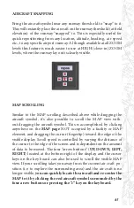
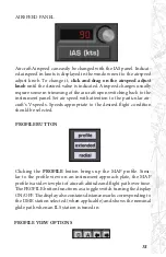
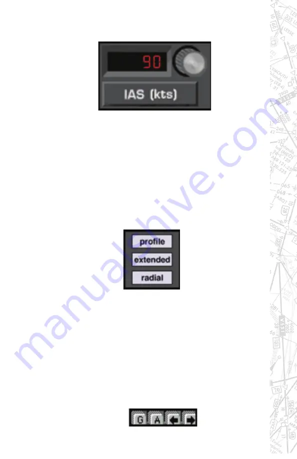
Aircraft Airspeed can easily be changed with the IAS panel. Indicat-

ed airspeed in knots is displayed in the window next to the airspeed 

adjust knob. To change it, 

click and drag on the airspeed adjust 

knob 

until the desired value is indicated. Airspeed changes usually 

require some re-trimming of the aircraft upon switching back to the 

instrument panel. Set air speed with attention to the particular air-

craft’s V-speeds. Speeds appropriate to the desired flight condition 

should be selected.

PROFILE BUTTON

Clicking the 

PROFILE 

button brings up the MAP profile. Simi-

lar  to  the  profile  view  on  an  instrument  approach  plate,  the  MAP             

profile is a side view plot of aircraft altitude and flight path over time. 

The PROFILE button functions as a toggle switch turning the display 

ON/OFF. The display also contains distance marks corresponding to 

the DME station selected (when applicable) and shows the nominal 

glide path when an ILS station is tuned in.

PROFILE VIEW OPTIONS

Summary of Contents for iGATE G500 Series

Page 1: ...iGATE ADVANCED AVIATION TRAINING DEVICE OPERATOR S HANDBOOK Copyright 1989 2018 by ELITE Simulation Solutions Model G500 Series ...

Page 2: ...ION SCREEN 31 SHUTTING DOWN THE IGATE 33 INITIAL ONFIGURATION 34 NAVIGATION DATABASES 36 ADJUSTING CONTROL SENSITIVITY 40 INSTRUCTOR OPERATOR STATION IOS 42 ELITE MENU STRUCTURE 43 MALFUNCTIONS PAGE OVERVIEW 44 METEO WEATHER PAGE OVERVIEW 45 METAR PAGE 46 DATA MODIFICATION PAGE 47 MAP PAGE OVERVIEW 48 CONTROL PAGE 49 INSTRUMENT PAGE 50 PROGRAM FEATURES 51 MAP PAGE COMMANDS 51 MAP INFORMATION 55 ...

Page 3: ...NS 93 MALFUNCTIONS PAGE 109 CONTROL PAGE 118 CONFIGURATION PAGE 125 NAV DATA MODIFICATION PAGE 131 EXTERNAL VISUAL DISPLAY GENVIEW ONLY 138 GENERAL INSTRUMENTS 140 IPAD CONFIGURATION PAGE 149 CONNECTING FOREFLIGHT TO ELITE 150 EFS 40 OVERVIEW 151 SHORTCUT CHECKLIST 156 IGATE CONFIGURATION MATRIX 157 ...

Page 4: ...authority for the use this training device in a Part 61 or 141 or 142 course of instruction is the Federal Aviation Administration General Aviation and Commercial Division AFS 810 800 Independence Avenue Washington D C 20591 REVISIONS For operational purposes this handbook should be kept in current status with revisions provided with software upgrades or hardware modifications Revisions to this ha...

Page 5: ...ems are also an available option Avionics King Silver Crown with GNS or GTN GPS naviga tion equipment Dual CPUs main computer image generator with sound system Number of IGs could change due to visual display options Closed fiber glass cockpit with adjustable seat s Overhead panels include aircraft appropriate hardware or simply lighting Twin and single engine turbine configura tions include side ...

Page 6: ...l provides life sized nav igation and engine instruments that allow for a correct scan pattern and complete aircraft start up run up and shut down The iGATE allows re configuration of aircraft through inter changeable software instrument masks switches and throttle quadrants Different classes and types SEL Complex MEL and Turbine are available options The Operator via the IOS can change the flying...

Page 7: ...anced visual scenery such as P3D and may be included with your training device COPYRIGHT Copyright 1989 2018 by ELITE Simulation Solutions Im Schoerli 1 8600 Duebendorf Switzerland All rights reserved Under copyright laws this manual may not be copied reproduced or dis tributed in any form or by any means in whole or in part without the written consent of the author ELITE Simulation Solutions AG Y...

Page 8: ... agreement Agreement carefully If you do not agree with the terms and conditions of this Agreement you should contact ELITE Sim ulation Solutions AG within 30 days from the invoice date NOTE The user of this manual is expected to know how to fly an aircraft It is not designed to teach instrument navigation or serve as a tu torial for starting running up flying or shutting down aircraft It will not...

Page 9: ... not use the software on another computer or loan rent transfer or assign them to another user except as part of the permanent transfer of the iGATE aviation training device 4 You may not copy the Software except that you may transfer the Software to a single hard disk for backup or ar chival purposes You may not copy the written materials 5 You may permanently transfer the iGATE Software and acco...

Page 10: ...nty so the above limitation may not apply to You 9 LICENSOR DISCLAIMS ALL OTHER WARRANTIES EI THER EXPRESS OR IMPLIED INCLUDING BUT NOT LIM ITED TO IMPLIED WARRANTIES OF MERCHANTA BILITY FITNESS FOR A PARTICULAR PURPOSE AND NON IN FRINGEMENT WITH RESPECT TO THE SOFTWARE AND THE ACCOMPANYING MATERIALS This limited warranty gives You specific legal rights You may have others which vary from state to...

Page 11: ...hever is applicable If any pro vision of this Agreement is found to be invalid by any court of competent jurisdiction the balance of this Agreement shall remain in full force and effect 14 If You have any questions concerning this Agreement or wish to contact Licensors for any reason please email info flyelite com or write to ELITE Simulation Solutions AG Im Schoerli 1 8600 Duebendorf Switzerland ...

Page 12: ... multi engine aircraft complex single and twin turbine aircraft Avionics configurations include the basic DG ADF HSI RMI EFIS and AHRS displays with support to the G1000 GNS and GTN series of Garmin GPS navigation systems All iGATEs support blue tooth interface with the most popular electronic flight devices such as Foreflight and JeppView Dual control iGATE Baron 58 Configuration with AHRS and GN...

Page 13: ...or mounted to a custom platform depend ing on space available or customer preference iGATEs come with either single seat or dual seat configuration with mechanical flight controls electrical dynamic control loading flight controls or a combination of pitch roll dynamic control loading with mechani cal rudder pedal controls Single control desktop iGATE C172 RG w Legacy InstrumentConfiguration iGATE...

Page 14: ...ttles like the masks are changed via thumb screws Switch panels on the iGATE console and aircraft specific controls located on the center console are quick change via Dzus style fas teners Switch panels and throttles connect to the trainers electrial grid via DB style connectors After the iGATE aircraft hardware has been changed the last step is to select the corresponding air craft on startup The...

Page 15: ...ed on the USB hub and on each USB control card for quick diagnosis Control cards also contain yellow transmit lights which indicate that data is being sent and received Other than reseating a card or unplugging and replugging a card s USB cord no other troubleshooting steps are recommended without the assistance and guidance of an ELITE qualified technician ...

Page 16: ...16 Single Seat iGATE Open Cockpit Configuration with one External Visual Dual Control iGATE with Optional Instructor s Cabin and Projection Visual ...

Page 17: ...17 Single Seat Twin Piston iGATE Closed Cockpit Configuration iGATE Dual Control with Center Console ...

Page 18: ...ent Humidity 20 to 80 non condensing 40 to 60 recom mended for optimum performance DIMENSIONS The cockpit footprint dimensions are shown in the following pictures For the iGATE cockpit plus one TV out of wind shield visual display the minimum sized room requirement would be 10 ft x 10 ft 3 05 m x 3 05 m Room ingress and egress must be considered plus room for the IOS desk and com puter system Actu...

Page 19: ...g urations to above level floors special equipment and required manpower These circumstances require methodical planning and must be discussed and agreed upon prior to delivery and installation Exact room requirements building access plans and additional costs must be discussed in advance or prior to any move or relocation Contact an ELITE representative for additional details ...

Page 20: ...20 iGATE with 3 screen projection display iGATE with Curved Screen Projection ...

Page 21: ...21 Desktop iGATE Twin Engine w G1000 Avionics Cockpit iGATE Twin Engine w HSI and RMI ...

Page 22: ...lable on all aircraft Autopilot flight director Altitude vertical speed preselect annunciator panel Radar altimeter not available on all aircraft Dynamic Control Loading Optional Single and dual pilot open or closed cockpit or desktop solutions Interchangable masks switches throttles and software pur chase NOTE See iGATE Configuration Matrix page 157 in this manu al for specific aircraft equipment...

Page 23: ...peed plot Flight Data Recorder with VCR style playback control Virtual airport facility directory Transponder tag w squawk code heading and altitude readout Spot WX station model display symbology wind temp visibility and pressure display Quick click and drag aircraft repositioning Real time and or recorded flight instrument presentation on IOS Map Screen Route planner Heading Distance MAP cursor ...

Page 24: ...OST computer Video cables connect the Instrument Monitors to the HOST Computer The Visual Com puter aka Image Generator s is connected to the HOST computer via LAN cable and has video cable s to the main LCD display s NOTE When the HOST computer is connected to the Internet ELITE technicians have the ability to perform a remote log in and conduct software upgrades make adjustments and diagnose iss...

Page 25: ...may be plugged into the HOST computer If the key is recognized and operating properly it should be identified in the Windows Device Manager Contact ELITE for additional support if needed WIBU Key Black or Green Color The ELITE or P3D visual scenery can be shown on any device that will receive a computer signal i e TVs monitors projec tors The HOST and VISUAL computers are custom built and configur...

Page 26: ...rm event and filters unstable power The number of UPS for the iGATE depends on the power requirement for a specific configuration For example if multiple TVs or projectors are used for the visual display an additional UPS would be required For one to two computers plus one TV or pro jector one UPS would suffice Apply power to the iGATE system by pressing the UPS power button NOTE The UPS should be...

Page 27: ...or after computer boot up is complete A Button to LAUNCH all software B Reboot all computers or SHUT DOWN all computers C Reboot or shut down SELECTED computers D Shows Computers ON LINE in green or OFF LINE in red E HELP button takes you to ELITE web Support if computer s fail to come on line after reboot IGATE MASTER CONTROL MODULE ...

Page 28: ... position yellow ring between the red knob and Emergency Stop decal visible NOTE In the event that the CL flight controls move erradical ly or uncontrollably during startup or operation twist the red emergency stop handle to the right to disengage power from the CL flight controls Center Console Emergency Stop and Freeze Button Location Emergency Stop Switch ...

Page 29: ...CH ELITE icon on the IOS Master Control Module Control Loaded flight controls pitch roll and or yaw will mo tor throught the full range of operation and return to its neutral position Allow the controls to move on their own accord do not interfere with its internal calibration 2 Choose the aircraft intended to fly by double clicking on the icon or high lighting the icon and clicking on CHOOSE STAR...

Page 30: ...ctory and this step may be unneces sary Calibrate only if necessary 4 Before the first flight it is important to calibrate the flight controls This is a simple exercise to teach the software the range of values from the pitch roll yaw brake and throttle movements This calibration is only required for the first flight and in the event that the flight controls have been disconnected and reconnected ie...

Page 31: ...ents aileron elevator rudders power quadrant and avionics in accordance with AC 61 136A are tested on startup ALL GREEN indicates that components are functioning proper ly Failures are indicated with red A red lettered component will not allow the pro gram to continue Press QUIT then REBOOT ALL at the IOS Master Control Module If the problem remains contact ELITE technical personnel ...

Page 32: ...Descent Altitude The flight controls switches levers and knobs perform the same function as their counterpart in the real aircraft At this point you can change frequencies adjust instruments and perform all proce dures for flight as you would in the actual aircraft The flight may be paused at any time by pressing the FREEZE button on the center console avionics panel or by using the main screen In...

Page 33: ...g box click SHUTDOWN ALL 3 When all computers have completed their automatic shutdown turn the system power off by hold the UPS power button NOTE DO NOT turn the power off to the instrument panels LCD monitors or TVs Projectors are the only componets that should be turned off separately because of cooling requirements To remove power completely from the system simply turn the pow er off at the Bat...

Page 34: ...above You get to the CONFIGURATION PAGE by right mouse clicking on the instructor s monitor when ELITE is running This brings up the ELITE Main Menu Click on CONFIGURATION PAGE or use the keyboard shortcut alt G Box 1 GENERAL SETTINGS The Configuration Page consists of nine sections as shown General Settings 1 Hardware Configuration 2 Controls 3 Units 4 Handling 5 Color for Digits 6 Aircraft Infor...

Page 35: ...pring mechanisms only change units of measurement for fuel and weight turn sounds on off adjust volume levels calibrate flight control devices NOT FOR CONTROL LOAD load new aircraft modules save instrument configurations where applicable Aircraft operational characteristics and limitations are also shown but cannot be modified ...

Page 36: ...n areas installed NOTE To have ELITE automatically start up default to the same aircraft and NAV area each time first make sure you are currently using the NAV area you would like for subsequent startups then turn OFF Ask for Navigation data bases at program start buttons Box 2 HARDWARE CONFIGURATION CHANGING SYSTEM SETTINGS Do NOT USE Changing Sys tem Settings unless instructed to do so by ELITE T...

Page 37: ... next to calibration The Calibra tion screen is divided into three sections or panels From left to right these are Limits Null zone and Helicopter respectively Follow these instructions to properly calibrate your flight control device s LIMITS Under Limits click the RESET button Now move your non CL controls through their FULL range of motion i e left right forward and backward to the stops The cr...

Page 38: ...size of the Roll Null zone To accept and store this setting hit ENTER or press the S key to return to the previously stored value Next press the P key on your keyboard and move the cyclic to adjust the size of the Pitch Null zone To accept this setting hit ENTER or press the S key to return to the previously stored value Next press the Y key on the key board and move the pedals to adjust the width...

Page 39: ...herently stable simulators are not For in ex perienced simulator pilots the most common difficulty is over controlling or getting used to the control sensitivity Practice basic flying maneuvers as you would in any new air craft transition before starting your IFR practice Remember the less is more adage and make small pitch and roll corrections for varia tion in altitude and or heading Do NOT chas...

Page 40: ...itivity Start with low to mid range Yaw usually re quires more dampening than pitch or roll Numbers between 0 00 no dampening and 0 20 maximum dampening change the sen sitivity of flight control devices SECOND MONI TOR Pressing the 2ND SCREEN button assigns the program menu to the 2nd monitor This allows someone sitting at the instructor s station easier access to the program menu and features ...

Page 41: ...down menu displaying all available changeable options for that section Drag the finger tip to the option desired and release the mouse button to make your selection The selected option will be indicated replacing the previous selection NOTE Some options may NOT be available even though there is a configuration option Contact ELITE if there are any doubts NOTE DO NOT MAKE CHANGES TO INSTRUMENT CONF...

Page 42: ...MENU button at the bottom right of your instructor screen is your access to the many features Click and hold on the MENU button to open the menu While hold ing your mouse button move the cursor to the menu selection and release As you move through each selection the item to be opened will be highlighted Keyboard shortcuts are listed beside their cor responding menu item For shortcuts hold the key ...

Page 43: ...ons see Program Features NOTE Keyboard shortcuts are shown to the right of menu title for example ALT Q on the keyboard will exit the program Shortcuts save time and allow instructor to change menus with out alerting the student Clicking on menu page will FREEZE simulation ELITE MENU STRUCTURE ...

Page 44: ...lures or create fail ure scenarios You have the opportunity to selectively or randomly fail individual instruments systems avionics engines gear hydrau lics and more NOTE Malfunction choices are aircraft specific and will vary according to the aircraft class and type ...

Page 45: ...O WEATHER PAGE The METEO meteorological Page is used to create the weather en vironment Various parameters such as visibility ceiling wind turbu lence icing pressure and temperature can be adjusted as desired ...

Page 46: ... available with the Lockheed Martin P3D visual scenery The METAR Page is used to download real time weather reports from METAR reporting stations for use in ELITE GenView When METAR weather is engaged activated to function in ELITE the weather dynamically changes when flying between METAR report ing stations and METAR time ...

Page 47: ...mple the US is divided into 9 areas x 50 540 modifications to the navigation database NOTE Modifications to navigation data will not be reflected in the GenView visual scenery Variation updates may change P3D visual scenery alignments NOTE If modifications new creations or existing facilities are not in compliance with FAA 14 CFR time can not be used toward instrument credit ...

Page 48: ...s the flight path in real time both horizontal and vertical profile views that can be replayed saved and printed for evaluation Over 15 map features can be displayed at 8 separate zoom levels The aircraft flight parameters magnetic head ing altitude and IAS can be set from the map page In addition you can also save and load training states or load Instrument Approach Scenarios IAS ...

Page 49: ...airport lighting features and runway markings Activate yaw control for us ing rudder pedals adjust fuel loading and aircraft weight configura tion and call sign Save and load training situations you created train ing states or load optional Instrument Approach Scenarios IAS ...

Page 50: ...obbs meter continues to run When first en tering ELITE the program is in the FREEZE mode as indicated by a red MENU triangle in the lower right corner of the screen When FREEZE mode is released the aircraft engine s will be in the state defined by the aircraft switches and throttles QUIT Selecting QUIT ends the program and returns you to the IOS Host Computer operating system ...

Page 51: ...setup the aircraft s initial position for a given flight or procedure monitor the flight path and to review the flight once you have fin ished flying The MAP page allows the instructor to monitor the progress of a flight in real time Similar in appearance to an IFR Low En route chart and laid out in approach plate like format the MAP page is familiar and easy to navigate The main part of the MAP p...

Page 52: ...items discussed in detail later in this section Aircraft HEADING Aircraft ALTITUDE Aircraft AIRSPEED Flight path CLEAR MAP Page PRINT Flight PATH save load ROUTE save load RADIAL compass rose display PROFILE view display Flight path REPLAY Aircraft REPOSition DATABASE Nav region load IAS Instrument Approach Scenario load AIRCRAFT STATE save load REPLAY settings FACILITY display ZOOM POSITION The r...

Page 53: ...l MAP view level which can be changed with the ZOOM function NAV DATA SYMBOLS The following Nav Data Symbols are visible on the Map page NDB with identification DME with identification ADF with identification VOR with identification FIX with identification marker Holding pattern with direction arrow Glide Slope indicator Glide Path Track Marker beacon location ...

Page 54: ...zer transmitter yellow Glideslope transmitter red Runway with displacement Airport symbol Communication frequencies NOTE Click on this box for other shortcuts MAP CURSORS The cursor changes for different functions on the MAP page Normal cursor fingertip Zoom in cursor Alt Key Zoom out cursor Shift Alt Zoom limit either enlarging or reducing Head ing Distance Shift key Add point Route planner Contr...

Page 55: ...ay s threshold In the example above several facilities nearly occupy the same location or are co located Information on these facilities is layered Clicking the same spot repeatedly cycles through these layers to re veal information about each specific facility The MAP Page is a virtual facility directory Just point click and hold MAP BORDERS Border types Flight Information Region FIR borders appe...

Page 56: ... aircraft If necessary scroll until the desired airport identifier is visible Select an airport and runway by clicking its identifier runway combina tion Notice that the airport runway lat long is now highlighted and the airport s name is indicated just below the scrollable view flying area The example above shows Donaueschingen EDTD selected Click on SELECT to position the air craft at the thresh...

Page 57: ...run way you would like to make the default then click DEFAULT Notice the airport identifier and runway selected EDTD 18 now appear in the Default Runway box at the bottom left To actually go to the default run way now or at any time in the future simply click on TO DEFAULT With a default airport runway now saved ELITE will automatically position the aircraft there on each subsequent startup assumi...

Page 58: ...f the runway For example Runway 27 and runway 9 at XYZ air port may have 109 90 as the ILS frequency If runway 27 is used for approaches the tower will turn off the ILS transmitter for runway 9 to prevent any false ILS indications In this instance you NOT ATC must deactivate or deselect the un used ILS should there be an ILS frequency conflict If you are flying the trainer in the vicinity of XYZ a...

Page 59: ...ointer will change to the select deselect icon 3 Using your mouse place the x over the apex of the ILS you wish to deselect and push the left mouse button The ILS anten na icon will change color from blue to amber 4 The navaid databox will display showing the ILS is disabled ...

Page 60: ...r will change to the select deselect icon 3 Using your mouse place the x over the apex of the ILS you wish to reactivate and push the left mouse button The ILS antenna icon will change color from amber back to blue 4 The navaid databox will display showing the ILS is now enabled ...

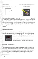
Page 61: ...g the aircraft symbol This is accomplished by clicking anywhere on the MAP page NOT occupied by a facility or MAP element and dragging the cursor fingertip toward the edge of the visible display Scroll speed is controlled by varying the distance of the cursor to the edge of the screen and is dependent on the amount of data to be moved The four arrow buttons UP DOWN LEFT RIGHT located at the bottom...

Page 62: ... I in O out and N normal keys respectively or magnifying glass buttons When you first enter the MAP page the display will be in normal zoom level defined as the 100 view Click on the ZOOM IN or ZOOM OUT but tons to increase or decrease the zoom level CUSTOM ZOOM LEVELS The zoom percentage is indicated on the display relative to the 100 view level You may zoom directly to an area of your choice cus...

Page 63: ... NOT be able to marquee a selection area to ZOOM in further Marquee selection and ZOOM IN are disabled when maximum ZOOM level is reached The ZOOM function is screen centered NOT aircraft centered If the aircraft is not in the center of the MAP page and you ZOOM IN the aircraft may be temporarily lost To find the aircraft and re center the MAP page to it click on the red aircraft symbol located nea...

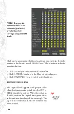
Page 64: ...ges Click STANDARD for a preset of active facilities TRANSPONDER TAG The tag itself will appear dark gray in color when the transponder switch is in the OFF or STBY standby position With the switch in the ON position the tag will turn green after sufficient time has elapsed for warm up The tag will turn red when the IDENT button has been pressed NOTE You may de termine which MAP elements facilitie...

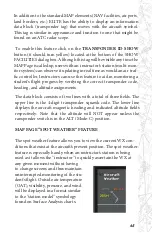
Page 65: ...ct transponder code heading and altitude assignments The data block consists of two lines with a total of three fields The upper line is the 4 digit transponder squawk code The lower line displays the aircraft magnetic heading and indicated altitude fields respectively Note that the altitude will NOT appear unless the ransponder switch is in the ALT Mode C position MAP PAGE SPOT WEATHER FEATURE Th...

Page 66: ...ton is an ON OFF toggle that will turn yellow when pushed in ON The spot weather data appears at the upper left corner of the MAP Page at the top of the shaded information display region NAVIGATION DATABASES All airports airport lighting fixes NDBs VORs localizers glide slopes communications data etc are contained in regional naviga tion data bases This data must be loaded for use in the program T...

Page 67: ...ur expe rience the better Make note of data that is suspected missing inac curate erroneous or otherwise anomalous and notify us with the details There can be several sources of navigation data with the trainer the data shown on the map screen provided by ELITE the GPS nav data provided by Jepp Garmin and the visual data provided by ELITE Lockheed Martin or other 3rd party visual provider All data...

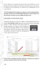
Page 68: ...viously for each additional data base CHANGING NAVIGATION DATA Navigation databases can also be added or changed quickly by click ing the DATABASE LOAD button at the bottom of the MAP page Choose a NAV database from those listed by double clicking on its name OR by clicking on its name then clicking OPEN to load Databases NOT listed which are located in other directo ries folders may also be used ...

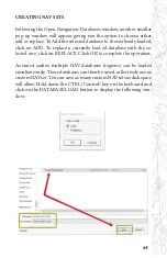
Page 69: ...eplace a currently load ed database with the se lected one click on REPLACE Click OK to complete the operation As stated earlier multiple NAV databases regions can be loaded simultaneously These databases can then be saved collectively as one custom NAVset You can save as many custom NAVsets as disk space will allow Hold down the CTRL Control key on the keyboard and click on the DATABASE LOAD butt...

Page 70: ...strument Approach Scenarios several add on regions available are scripted approach exercises own in a simu lated ATC environment Each scenario begins with the aircraft at a predetermined altitude and generally positioned 15 20 miles from the IAF Initial Approach Fix of the selected approach One sample scenario is included with each ELITE package an ILS approach into Champaign Urbana Illinois The a...

Page 71: ...lli nois Wisconsin IAS package make sure to load the IASEC3 data base The autopilot is ON by default at the start of each scenario Keep the autopilot ON briefly to let the aircraft stabilize After the aircraft sta bilizes you can continue to fly the scenario utilizing the autopilot or you can disengage the autopilot and fly the aircraft manually Approach plates for the Instrument Approach Scenario...

Page 72: ... switch in a real aircraft sometimes requested by ATC to verify communication CTRL S Press CTRL S to disable the automatic setting of radios by the virtual instructor see next section INSTRUCTOR HELP At the beginning of the each scenario the program will ask if you would like to have the help of an instructor By answering yes to this option you will be inviting a virtual instructor into the cockpi...

Page 73: ...seful when you want to practice the same approach procedure flight or sit uation repeatedly Individual pilots and instructors often create a library of state files which allow them to conveniently return to a desired lesson without having to setup the aircraft again manually State files can be saved at any time Before saving a state file make sure that the aircraft is set up just the way you want ...

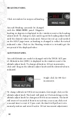
Page 74: ...NEL Aircraft Altitude can easily be changed with the TRUE ALT pan el Altitude in feet MSL is displayed in the window next to the altitude adjust knob To change altitude in 10 foot increments click and drag on the altitude adjust knob until the desired value is indicated Single click for 500 foot increments To change altitude in 500 foot increments first single click on the altitude adjust knob The...

Page 75: ...ttention to the particular air craft s V speeds Speeds appropriate to the desired flight condition should be selected PROFILE BUTTON Clicking the PROFILE button brings up the MAP profile Simi lar to the profile view on an instrument approach plate the MAP profile is a side view plot of aircraft altitude and flight path over time The PROFILE button functions as a toggle switch turning the display O...

Page 76: ...ation as follows Yellow lines half scale Red lines full scale ALTITUDE GRID The A altitude grid button toggles the altitude grid lines These lines are used in conjunction with and are extensions of the altitude scale markings on the right side of the profile display PROFILE SCROLL The two arrow buttons are used to scroll the profile view left and right respectively and operate independent of the m...

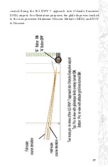
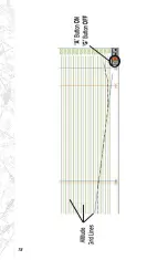
Page 77: ...77 created flying the ILS RWY 7 approach into Orlando Executive ORL airport For illustration purposes the glide slope was tracked to the non precision Minimum Descent Altitude MDA and NOT to Decision ...

Page 78: ...78 ...

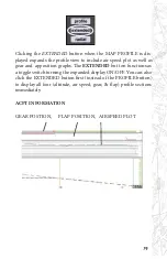
Page 79: ... as gear and apposition graphs The EXTENDED but ton functions as a toggle switch turning the expanded display ON OFF You can also click the EXTENDED button first instead of the PROFILE button to display all four altitude air speed gear flap profile sections immediately ACFT INFORMATION GEAR POSTION FLAP POSITION AIRSPEED PLOT ...

Page 80: ...cal line appears at the selected location in the profile and positions the red air craft symbol on the main MAP screen to the place on the aircraft track corresponding to the selected profile loca tion clicked on Accompanying the red aircraft symbol is the ACFT Information box with data on location altitude heading airspeed vertical speed gear and flap positions The red aircraft symbol and ACFT In...

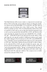
Page 81: ...t to BEARING TO or RADI AL and DISTANCE have been replaced by actual values Click and drag the red aircraft symbol to different positions and watch the values change in these windows to reflect the actual BEARING TO or RADIAL from and DISTANCE relative to the selected FIX or NAV aid This feature displays the exact aircraft location relative to the selected FIX or NAV aid and is helpful for quick e...

Page 82: ...ht This same data can then be used to replay the last 60 minutes of the flight or saved as a path file for replay at any point in the future PLAY PAUSE BUTTON CLICK to START replay CLICK again to PAUSE replay Replay can begin at any point in the recorded flight path Select a different Re play start point by moving the red aircraft symbol using the Rewind and Fast Forward buttons REWIND BUTTON CLIC...

Page 83: ...of the cockpit environment entirely Installations with a remote Instructor s Station are common and of ten purposely designed to prevent the student from peeking at the Instructor s Station monitor otherwise known as the Instant Situa tional Awareness Indicator Such systems require an instructor to have to look some distance over the shoulder of the student if he she wants to observe the instrumen...

Page 84: ...lly relates to and is used to define how the instruments will be displayed on the MAP page You can control if when where how the instruments are dis played Change or modify the initial replay settings as desired These set tings can be changed modified at any point in the future by simply clicking on the set tings button at the bottom of the MAP page under REPLAY ...

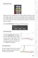
Page 85: ... displayed and or replayed on the MAP page for analysis Click the PATH button to bring up the following box SAVE BUTTON To save the flight path just flown click the SAVE button to bring up the Save Path files window Type a name in the File name box BCRWY25 in the example for the flight path file then click Save to complete the operation LOAD BUTTON To load a flight path click the LOAD button and se...

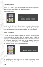
Page 86: ...her on in this chapter PRINT BUTTON Clicking the PRINT button captures an image of the MAP page Once captured you can then print the image or save it to disk for viewing later Set MAP ZOOM level and select PROFILE as desired to customize the MAP to your taste before clicking the PRINT button To print the MAP page click PRINT and follow the print dialog boxes specific to your operating system SAVE ...

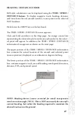
Page 87: ...ll appear In addition the TIME SPEED DISTANCE information box appears as shown on the next page The upper portion of the TIME SPEED DISTANCE information box contains the actual location of the aircraft and selected point mouse position displayed as coordinates in degrees lat long The lower portion of the TIME SPEED DISTANCE information box contains magnetic track aircraft heading wind speed direct...

Page 88: ... route planner is a special tool for quick flight planning Use the keyboard commands described on the next page to design a route ADD POINT Push the CTRL control key on the keyboard and the cursor chang es to add point Click on any location from which you will start your route and you get the first route point 1 The next click dis plays route point 2 and so on until you release the CTRL key To add...

Page 89: ...e effect ROUTE INFORMATION Click and hold on individual route points to get route and leg infor mation Point coordinates as well as track and distance information are displayed in an accompanying window as long as the mouse but ton is held down SHORTCUTS To display the Shortcuts Information window click on the but ton The Short cuts window will open and display all shortcuts key combinations that ...

Page 90: ...ever override this automat ic selection by manually selecting the active runway following the procedure below Press ALT A to engage or disengage mode Once engaged enables you to manually select ELITE s active runway by clicking on the threshold of desired runway runway color changes to green to iden tify that it is active You can change your selection as many times as you like while the manual sel...

Page 91: ...a virtual A FD airport facility directory Click the com box icon and hold on the symbol in the center of the runway complex A Communication box will come up displaying information and num ber of frequencies available at this airport FREQUENCY COLUMN While holding down the mouse button move the cursor to the SHOW corner located at the top right of the Communication box All frequency information ava...

Page 92: ...rvice Station GND Ground Control GTE Gate Control HEL Helicopter Frequency INF Information MUL Multicom ODP Parameters French Radio OPS Operations RDO Radio RDR Radar Only Frequency RFS Remote Flight Service Station RFSS RMP Ramp Taxi Control RSA Airport Radar Service Area ARSA TCA Terminal Control Area TRS Terminal Radar Service Area TRSA TWE Transcribed Weather Broadcast TWEB TWR Air Traffic Con...

Page 93: ... and practicing holds in strong winds and turbulence without a problem The METEO Page is extrememly flexible and provides an opportuni ty for an almost infinite amount of weather possibilities Please feel free to experiment METEO GENERAL LAYOUT The METEO Page is rather comprehensive and might look a bit in timidating at first Actually it is set up quite logically and is easy to use once you unders...

Page 94: ...94 We will examine each of these elements in greater detail in upcoming sections METEO CLOUD SECTION METEO WIND SECTION ...

Page 95: ...the desired weather parameter s Repeat this in the same way to set the To parameters It is important to remember that the inten sity or rate of change of the weather is also controlled by the proce dure described in the previous section For example large parameter variances in relatively short time intervals produce rapidly changing weather as opposed to small parameter variances over longer time ...

Page 96: ...are reflected it is easy to get a quick picture of the weather with just a glance STATIC WEATHER To set static unchanging weather use the To weather column ONLY and do NOT set in a time interval If a time interval is set then the From weather automatically becomes the current weather NOTE Remember it is possible to use any combination of static and dynamic weather settings ...

Page 97: ...e that the top of the bottom wind layer is also the base of the mid wind layer The top of the mid wind layer is also the base of the top wind layer TRANSITION ZONES Transition Zones are available for each of the three Cloud Layers and can only be selected when overcast OVC coverage is in use A Transition Zone creates a gradual visual transition to and from the cloud conditions existing above or be...

Page 98: ...anging winds it is possible to have the winds change in a clock wise or counter clock wise manner The CW clockwise button is a toggle switch that when depressed will change to CCW counter clock wise Sim ply leave this button up unselected for clockwise rotation of the changing winds or down selected for counter clockwise rotation Wind direction is always MAGNETIC and can be set in 10 incre ments b...

Page 99: ...e level 1 light through 12 extreme is set by click ing the UP and DOWN arrow buttons Separate turbulence levels can be set for each of the three corresponding wind layers CEILING STANDARD VIEW Ceiling in feet Above Ground Level is set by clicking the UP and DOWN arrow buttons To make the ceiling variable with respect to the selected height simply press the button ...

Page 100: ...00 40 000ft Cloud Layers 2 and 3 Select visibility using UP DOWN arrows as desired NOTE Visibility can only be adjusted if cloud coverage is set to OVERCAST With an OVERCAST layer programmed selected visibility will be come the controlling visibility above the TOP of the OVERCAST up to the next highest OVERCAST layer programmed This then becomes the visibility between the OVERCAST layers If no hig...

Page 101: ...ing the CAVOK button in ELITE with Cloud Layer 3 Base set to less than or equal to 5100ft MSL will also set cloud coverage to Sky Clear SKC in addi tion to changing visibility to 30 statute miles Preset buttons can be used to jump quickly to 1 2 1 and 30 statute mile values respectively and then further adjusted as desired Visibility value selected will become the visibility from the surface up to...

Page 102: ...in Statute Miles and or Meters can be set by clicking the appropriate UP and DOWN arrow buttons In addition there are three combination visibility ceiling presets that allow you to quickly choose Precision Non Precision or CAVOK minimums respective ly Once selected these preset values can then be further adjusted as necessary These preset minimums are as follows Precision 200ft ceiling 1 2 Mile vi...

Page 103: ...cated altitude If the student doesn t ask you for the local altimeter setting or tune in the ATIS he she will get a big surprise on the approach TEMPERATURE Temperature in degrees Celsius can be adjusted by clicking the UP and DOWN arrow buttons Note that this is NOT setting the tem perature directly but is actually adding to or subtracting from the ISA International Standard Atmosphere values If ...

Page 104: ...o most im portant things in aviation are the next two If conditions are ripe for icing then be on alert for subtle performance changes and or indica tions that may be symptomatic of icing The goal of any simulation is to sharpen your situational aware ness This is not only geographic positional awareness but how are things going awareness ELITE s intent is not to prepare you for how to exactly rea...

Page 105: ...ensity chosen anytime the aircraft is in visible moisture and at a temperature of approximately 32 degrees Fahrenheit and lower For the purposes of the simulation visible moisture is defined as 1 4 statute mile visibility and less or flying in an overcast OVC layer With either icing implementation intensity levels affect icing fac tor in the following ways Light icing factor goes up to 50 in 60 mi...

Page 106: ...o state are extremely powerful Let s say you have set up a weather scenario on the ME TEO Page You get it just exactly the way you want it with all the parameters set but you would also like to save this Meteo state for future use Simply click on the SAVE button to open the Save Meteo files dialog box Type a name in the File name box then click Save to complete the operation To load this Meteo stat...

Page 107: ... and To parameters If for exam ple you set the bottom layer winds to increase between 005 and 015 minutes and the ceiling to lower between 010 and 020 minutes these changes will not begin to take effect until the Reference Meteo Time reaches 005 minutes At 005 minutes the bottom layer winds will begin increasing and continue increasing until 015 minutes where the To parameter values will have been...

Page 108: ...eated One important point to keep in mind is that if you have been flying a given sim session for an extended period of time then set up some dynamic weather make sure to either RESET the Ref erence Meteo Time or set time intervals in the future If the time intervals set are before the Reference Meteo Time then the changes will never occur ...

Page 109: ...tips The MALFUNCTIONS Page is used to create failure scenarios The ability to setup and practice realistic failures are one of the most powerful features in any simulation Many of these failures would be impractical impossible or unsafe to recreate in an actual aircraft Yet exposure to these same situations in a simulated environment can give you invaluable experience the airlines and military hav...

Page 110: ...by pressing the associated ARM button s Note that the ARM button will change to FAIL when that particular item has actually failed Click on the FAIL button once to RESET the item to ARM Click again to CLEAR the failure INSTRUMENTS AND SYSTEMS FAILURES Individual instruments can be failed in two different ways 1 Freeze instrument maintains indications 2 Gradual more realistic failure sequence occur...

Page 111: ...itude Indicator to gradually fail at some point between seven and fifteen minutes from now we would simply enter 07 and 15 respectively in the Between column and press the ARM button in the Gradual column next to AI If this were done at the start of our flight the Ref Failure Time would already be set to zero But if we had been flying for some time and wanted the failure to occur be tween seven an...

Page 112: ...etween windows If we had been flying for fifteen minutes and wanted the Pitot Tube to freeze over with an ac cumulation of ice three minutes from now we would simply enter 18 and 18 respectively in the Between column When the Ref Failure Time reached 18 minutes the Pitot Tube would freeze over and we would observe a subsequent erroneous indication on the Airspeed Indicator a good time to turn ON P...

Page 113: ... setup in much the same way as previously dis cussed except that immediate failures are invoked by using the ARM buttons in the immediate column To set a specific failure time or a failure time window interval you must use the ARM buttons in the Timed column ...

Page 114: ...engine instruments in his her scan is to invoke an Oil Pressure failure and see if the student notices the pressure dropping To really bring the point home set up a scenario in which the Oil Pressure drops followed by an increase in Oil Temperature and subsequent power loss NOTE The Power Loss window shows the power available NOT the percentage of power loss If for example the power loss window we...

Page 115: ...he number of failures you would like to occur If for example we entered in a fail ure time window of between 3 and 12 minutes then entered 2 in the Instruments window ELITE would randomly fail two of the six instruments each at some random time between 3 and 12 minutes NOTE Engines does NOT refer to the number of engines but rather to the number of possible engine failures Depending on the aircraf...

Page 116: ...as OilPressLoss then click Save to complete the operation To load this failure state or any other in the future just click on the LOAD button to open the Open Malfunction files dialog box Select a failure state from those listed previously saved and click Open RESET TO ARM The Reset to ARM and Clear all failures buttons provide a quick way to RESET the MALFUNCTIONS page as required Use the Re set t...

Page 117: ...k to zero minutes This is used in conjunction with the fail ure time window interval set tings as described previously The MALFUNCTIONS page is extremely flexible and provides an opportunity for an almost infinite amount of failure scenario possi bilities Please feel free to experiment NOTE different aircraft modules may show different malfunc tion options based on the systems of that aircraft ...

Page 118: ... that item Simply click on the item to display related help tips Use the CONTROL page to configure air craft load and fuel control visual settings load Instrument Approach Scenarios save load STATE files and more VISUAL DATE TIME PANEL Use the Visual panel to con figure ELITE s visual display settings Everything from Time of Day to the amount of runway environment de tail displayed can be changed ...

Page 119: ...nding on aircraft location within the specific Time Zone flown in and Daylight Saving Time LMT may be off by as much as 2 Hrs Use this time only as a reference for setting day night flying conditions To change time of day click and drag on hours minutes adjust knobs located below LMT display window PRESET LEVEL OF DETAIL GENVIEW ONLY Software performance is directly related to the computer hard wa...

Page 120: ...omputers The Visual Detail panel allows you to tweak these settings to get the best performance possible from a given system Simply CTRL click on any one of the LOW MEDIUM or HIGH buttons turns orange and its corresponding Visual Detail pre set will become activated Presets can then be modified manually as de sired by selectively turning ON OFF items in the Visual Detail panel The selected LOW MED...

Page 121: ...in dow The knob will show an orange dot When you use the knob increments will be by 500 ft Click again in the window to deactivate Feature will deactivate itself in 5 seconds if there is no activity Set indicated airspeed knots ENABLING FUEL IMBALANCE When ENABLED allows for flight characteristics to be affected by lateral asymmetric fuel loading Set aircraft load weight change from KGs to LBS on ...

Page 122: ...n etc In addition you have the option of storing Navigation Meteo weather and Malfunction data as well The saved state file can then be loaded at any time in the future and instantly position the aircraft where it was with the same settings when the file was saved State files are very useful when you want to practice the same ap proach procedure flight or situation repeatedly Individual pilots and...

Page 123: ...e an airport identifier or nearby Navaid and brief description such as ORL ILS RWY 7 Low Ceilings Even if you ha ven t loaded this file in a while it will be easily identified as the ILS approach into Orlando Executive s runway 7 with low ceilings This is much better than My first ILS SAVING STATES To save the current aircraft state click the SAVE button to bring up the Save State file window Type ...

Page 124: ...e Open State files window Highlight the state file you wish to load from those listed then click OPEN TIME FLOWN PANEL The Time Flown panel always indicates the elapsed time ELITE has been flown Time automatically stops when the flight is frozen or while not flying on the Instrument panel ...

Page 125: ...related help tips Use this page to configure flight controls hardware instrumenta tion and sound Some of these have already been covered during the Startup procedures in Chapter One STATE FILES When the Ask for State File at Program Start button is ON ELITE will display a dialog box on every startup allowing you to choose any training State File previously saved You will be positioned with the sam...

Page 126: ... OK with the password field blank TIME DIFFERENCE LT TO UTC For ELITE to properly calculate daylight sunrise and sun set times you must set the difference between your local time LT and UTC Zulu time First verify that your computer s clock is set correctly Click on the SET button Calculate your local time using 12 00UTC as a reference For example in Orlando Florida UTC 5 you would set the local ti...

Page 127: ...l appear during program start advising the system may NOT be used for flying credit allowed by the FAA ACTIVATING FAILURES WITH KEYBOARD Failures Activating with Keyboard ON allows the user to fail specific instruments and systems via the keyboard completely independent of the simulation This is especially useful for system configurations not incorporating a separate graphical instructor s station...

Page 128: ...isplayed for weight and fuel values as desired Weight in pounds or kilos Fuel in liters U S gallons or Imperial gallons CHANGING COLOR OF NUMBERS For readability you can change the color of numbers shown on all pages except the instrument panels Click on RED or YELLOW as desired ...

Page 129: ...your ELITE sound experience NOTE Engine sound can also be switched ON or OFF with the E key on the keyboard 3D SOUND For ELITE technicians only The iGATE sound will be properly configured before installation Do not change settings without con sulting ELITE technical support personnel Depending on hardware configuration 3D sound ON allows for an enhanced audio experi ence on 3D compatible sound sys...

Page 130: ...130 ...

Page 131: ...dify up to 200 facilities fixes NAVaids or holding patterns in each navigation data base worldwide This NAV DATA is inherent to ELITE software only Only modification of variation will be relfected in the P3D visual scenery Changes to runways and lighting will NOT CREATING FACILITIES The desired facility can be created by clicking on the appropriate button When a button is clicked a window will app...

Page 132: ...e original data base file on your hard disk but only a copy of the data If you choose to delete a self created facility the pop up window will ask you if you really want to irrevocably delete your self created fa cility After creating modifying or deleting a facility click on the OK but ton to confirm the changes If you click on the CANCEL button all previous instructions are cancelled and you retu...

Page 133: ...ginal facility that had been deleted hold the ALT key while clicking on the DELETE button The following pop up window will appear on the screen You can now undo a previous facility deletion and it will once again be displayed on the Map Deleting an existing original facility counts as one change Delet ing a self created or modified facility releases one for further use Undeleting a previous deleti...

Page 134: ... the runway threshold When facilities are in the same location or covered by other ones click on the same spot once more and information about the next facility will ap pear In the example above several facilities nearly occupy the same lo cation or are co located Information on these facilities is layered Clicking the same spot repeatedly cycles through these layers to re veal information about e...

Page 135: ...135 ADDING FACILITIES ...

Page 136: ...136 ...

Page 137: ...137 ...

Page 138: ...ealism of flight by providing 3 D obstructions to visibility cloud coverages and several transition zones or layers for IFR MVFR SVFR or VFR on top Utilizing actual downloadable METAR reports you can create a real time flight experience and save the most challenging weather scenarios for recurrent training GENVIEW VECTOR DATA Elements in the digital elevation model depicts rivers lakes high ways r...

Page 139: ...utton Press the ALT key and drop the aircraft at the runway end and it will reposition to the taxiway parallel to the active runway c Go to the MAP Page Click on the aircraft symbol and hold the mouse button Press the SHIFT key and drop the aircraft at the run way end and it will reposition perpendicular to the active runway 3 The length of the runway determines the width of the taxiways longer ru...

Page 140: ... as well as the red line have the standard meaning True airspeed may be calculated by applying the usual techniques assuming ISA temperature If the air speed indication should decrease without speed reduction the pitot may be iced In order to prevent pitot icing turn the PITOT HEAT to ON ARTIFICIAL HORIZON GENERAL INSTRUMENTS ...

Page 141: ...vironment panel on the Meteo screen VERTICAL SPEED INDICATOR The Vertical Speed Indicator VSI in dicates the rate of climb or rate of descent Vertical Speed is not instan taneous and will exhibit trend and lag effects TURN INDICATOR The Turn Indicator Turn coordinator is actually a combination of two instru ments The aircraft symbol indicates rate of roll and rate of turn and is proportion al to t...

Page 142: ...ator HSI is connected to the NAV1 receiver It consists of a turning compass card a yellow course point er CDI turned by the left rotary dial an orange heading bug moved by the right rotary dial and a yellow glide slope mark on both sides when on ILS The actual course is indicated by the white lubber line on the compass card The HSI replaces the standard direction al gyro in the aircraft s panel co...

Page 143: ...y the OBS knob in the conven tional manner The RADIO MAGNETIC INDICATOR RMI incorporates a slaved self rotating compass card a green single pointer and a yellow double pointer The green single pointer may be switched between NAV1 receiver and NAV2 receiver The double line pointer is pointing to the ADF receiver If any navigation set is not receiving a valid signal from a station the corre sponding...

Page 144: ...cted by HDG knob AVIONICS ELITE is equipped with an ALT VSI reselect Marker Beacon Lights Audio Panel either a Garmin 430 or 530 the COMM1 NAV1 func tion is provided in the GPS unit NAV2 COMM2 KX 165 TSO ADF KR27 and a Flight Director Autopilots KFC 150 Optional avionics include EFS 40 or E500 ELITE AHRS iGATEs are also available with OEM Garmin GNS 430W GNS 530W GTN 650 GTN 750 or G1000 Using rea...

Page 145: ...iver is activated the actual radial from the VOR station is displayed in place of the standby frequency While in the radial mode di rect tuning of the active frequency is available using the methods described above There is of course no radial available when an ILS frequency is tuned ADF RECEIVER The Automatic Direction Finder Receiver ADF in ELITE se lects a Non Directional Beacon NDB in the freq...

Page 146: ...e the corresponding marker lamp flashes The duration of the marker reception as well as the reception range depends on the type of marker TRANSPONDER Transponder KN 67A Push button to right to change number IDENT Change transponder mode Click mouse on knob and drag left or right to activate tran sponder features Change transponder code Click mouse on knob and drag left or The Transponder is a radi...

Page 147: ...HSI flight director if equipped or using VOR 1 OBS and VOR 2 OBS In addition the altimeter setting and radar altimeter bug may also be set as necessary The course and heading bug knobs are found in the typical location on the instrument panel by the corre sponding instrument The MDI is for the Magnetic Deviation Indi cator Course Heading Control Panel ...

Page 148: ...148 ...

Page 149: ...the iPad Configure screen by right clicking on your map or instrument panel and selecting iPad Configure or use the ALT Y shortcut The following screen will appear Notice that each column of this screen is for a different supported iPad application You only need to work within the iPad applica tion you are using You can use more than one iPad application however if you choose to NOTE A WIFI networ...

Page 150: ... the iPad Configure Page on the IOS or ALT Y 4 Press Send under the Broadcast Foreflight column 5 Start Foreflight on your iPad 6 Press the more button then go to devices ELITE will appear as a device 7 Select the ELITE device and enable it The ELITE device will display as connected Additional information and illustrations on connecting other apps can be found on the ELITE website http support fly...

Page 151: ...ded EFS Control Module For the purposes of this manual the intent is not to provide a complete pilot s guide but to give an introduction to and abbrevi ate commands associated with the EFS 40 For complete instruc tions refer to Bendix King EFS 40 50 Pilot s Guide Manual ELECTRONIC FLIGHT INSTRUMENTATION SYSTEM EFS 40 PILOT S GUIDE ...

Page 152: ...152 Abbreviate Operation of the EFS Control Panel ...

Page 153: ...igures White On side approach and navigation data Green Cross side NAV data Yellow On side non approach navigation data LNAV Cyan On side commanded data Green Cross side commanded data Yellow Selected heading DME HOLD annunciation Orange Selected source Matches NAV data color Selected active route flight plan Green Cross side selected active route flight plan Yellow Held DME distance display White...

Page 154: ...154 EFS Symbol Definition ...

Page 155: ...155 EADI Symbology Definition ...

Page 156: ...ubdirectory Dump in file system C ProgramFiles Elite Elite Pilot 8 Dump The file name is Dump YYYY MM DD hh mm ss bmp This file can be printed after the session without interfering with the simulation MODIFY SIMULATION SPEED Control ALT S Reduce simulation speed Control ALT F Increase simulation speed MAP SHORT CUTS I Zoom In O Zoom Out N Zoom to 100 Normal zoom level C Center A C symbol on map AL...

Page 157: ...ssna 172R Cessna 172RG Cessna 182S Beech Bonanza A36 Piper Arrow IV Piper Archer III Beech Duchess 76 Beech Baron 58 Piper Seneca III Beech King Air B200 Pilatus PC 12 GLASS Garmin G1000 Cessna 172S G1000 Cessna 182 G1000 Diamond DA40 Diamond DA42 Beech Baron G58 Controls Instrumentation Analog GPS Control Type ELITE iGate Configuration Matrix as of 8 May 2018 ...

Reviews: