


64
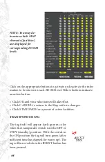
Click on the appropriate buttons to activate or deactivate the infor-
mation to be shown in each ZOOM level. Yellow buttons indicate
an active button.
• Click OK and your selections will take effect.
• Click CANCEL to return to the Map with no changes.
• Click STANDARD for a preset of active facilities.
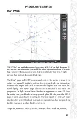
TRANSPONDER TAG
The tag itself will appear dark-gray in color
when the transponder switch is in the OFF or
STBY (standby) position. With the switch in
the ON position the tag will turn green (after
sufficient time has elapsed for warm up). The
tag will turn red when the IDENT button has
been pressed.
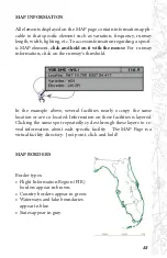
NOTE: You may de-
termine which MAP
elements (facilities)
are displayed for
corresponding ZOOM
levels.
Summary of Contents for iGATE G500 Series
Page 20: ...20 iGATE with 3 screen projection display iGATE with Curved Screen Projection ...
Page 21: ...21 Desktop iGATE Twin Engine w G1000 Avionics Cockpit iGATE Twin Engine w HSI and RMI ...
Page 78: ...78 ...
Page 130: ...130 ...
Page 135: ...135 ADDING FACILITIES ...
Page 136: ...136 ...
Page 137: ...137 ...
Page 148: ...148 ...
Page 152: ...152 Abbreviate Operation of the EFS Control Panel ...
Page 154: ...154 EFS Symbol Definition ...
Page 155: ...155 EADI Symbology Definition ...


