background image

115

.

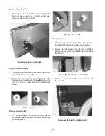
Backguard trim screws

4. Remove the two screws in front, the eight screws in

back, disconnect the wires from the oven light and
fluorescent switches and lift the trim off.

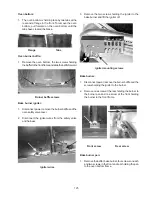
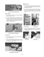
Back panel of backguard:

1. Disconnect power from range, remove the backguard

glass and trim.

2. Remove the four screws holding the electronic oven

control bracket to the back panel.


EOC backpanel screws

3. Remove the four screws holding the splash panel to

the back panel.


Splash panel screws

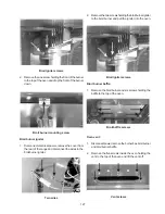
4. Remove the two screws holding the back panel to

the bodysides.

Backpanel/bodyside

screws

5. Remove the screw holding the ground wire to the

back panel.

Ground wire screw

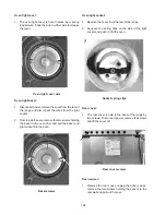
6. Tip the top of the back panel out, release the wiring

from the bottom of the panel and lift the panel off.

Wiring

Summary of Contents for 30" GAS FREESTANDING RANGES

Page 1: ...1 White Westinghouse ELECTROLUX HOME PRODUCTS NOR TH AMERICA SERVICE MANUAL NEXT GEN 30 36 GAS FREESTANDING RANGES 5995361531 April 2001 1111111 ...

Page 2: ...supply Turn off the water supply 3 Never interfere with the proper operation of any safety device 4 USE ONLY REPLACEMENT PARTS CATALOGED FOR THIS APPLIANCE SUBSTITUTIONS MAY DEFEAT COMPLIANCE WITH SAFETY STANDARDS SET FOR HOME APPLIANCES 5 GROUNDING The standard color coding for safety ground wires is GREEN or GREEN with YELLOW STRIPES Ground leads are not to be used as current carrying conductors...

Page 3: ...rface burner valve 19 Electric ignition burners 19 Air shutter oven burner 19 Air shutter broil burner 19 Make sure the range is level 19 Converting to LP 20 25 Tools Required for LP conversion 20 Converting the pressure regulator 21 Converting surface burner to LP 22 Converting the oven and broil burners 23 Reconnect gas and electric supply to range 23 Air sutter ajustment oven and broil burners ...

Page 4: ...0 control 39 To set the clock 39 To set the minute timer 39 To change the minute timer while in use 39 To set the control for baking 39 To change the oven temperature after baking has started 40 To set the oven control for broil 40 How the ES 100 system operates 40 Bake 40 Broil 41 Calibration 41 To change calibration 41 Troubleshooting 41 F1 code 41 F3 code 41 Control will not program 42 Blank di...

Page 5: ...300 system 51 For a silent control panel 51 Temperature conversion 51 To set the clock 51 To set the minute timer 51 To change the minute timer while it is in use 52 To cancel the minute timer before the set time has run out 52 To set the controls for bake 52 To change the oven temperature after baking has started 52 To set control for continuous bake or 12 hour energy saving 52 To set the control...

Page 6: ...1 Minute timer 61 To set the minute timer 62 To change the minute timer while in use 62 To cancel the minute timer before the set time has run out 62 Oven lockout feature 62 To active the oven lockout 62 To reactivate oven operation 62 Temperature display Fahrenheit or Celsius 62 Silent control operation 62 To change from sound to silent operation 62 Preheat 62 To change preheat temperature while ...

Page 7: ... control system 73 How to program the ES 450 73 Clock 73 Changing between 12 or 24 hour time of day display 73 Continuous bake or 12 hour energy saving 73 Minute timer 74 To change the minute timer while it is in use 74 To cancel the minute timer before the set time has run out 74 Oven lockout feature 74 To active the oven lockout 74 To reactivate oven operation 74 Temperature display Fahrenheit o...

Page 8: ... heat 82 Broil burner operates but bake burner does not heat 82 Bake burner operates but broil burner does not heat 82 Self cleaning 82 Oven door does not lock when the oven is programmed for clean 82 Oven door locks when the oven is programmed for clean but the oven does not heat 83 Lock motor runs continuously 83 Door latch is partly closed with door open 83 Sample schematic for ES 450 Control s...

Page 9: ...r 94 To set the warmer drawer control 94 How the warmer drawer circuit works 94 Troubleshooting 94 If the element does not heat 94 If the element heats during preheat then stays off until the temperature drops to about 130 degrees 95 Element does not cycle off 95 Warmer drawer is slow to preheat 95 Warmer drawer heats but indicator light does not glow 95 SECTION D DISASSEMBLYAND REPLACEMENT OF PAR...

Page 10: ... cover 107 Removing back cover 107 Removing heat shield 107 Removing pressure regulator 108 Removing top burner igniter spark module 108 Removing lock motor assembly 108 Removing oven sensor 109 Door switch and rod removal 109 Removing convection and speed bake motor assemblies 109 Removing bodyside panels 110 Storage drawer 111 Removing storage drawer front panel 111 Removing inside drawer panel ...

Page 11: ...the wool shield 122 Removing the glass package 123 Removing inner door liner 123 Removing oven door springs 123 Removing oven door hinge 123 Removing storage drawer 123 Removing storage drawer handle 123 Removing storage drawer panel 124 Removing storage drawer rollers 124 Removing storage drawer rails 124 Removing storage drawer front panel 124 Removing the oven bottom 125 Removing bake burner ba...

Page 12: ...nt spec 3 2 to 3 6 amps Incremented unit number Production week Last digit of production year Product identification Manufacturing Facility RTD SCALE Temperature F Resistance in Ohms 32 1 9 1000 4 0 75 2 5 1091 5 3 250 4 4 1453 8 9 350 5 4 1654 10 8 450 6 9 1852 13 5 550 8 2 2047 15 8 650 9 6 2237 18 5 900 13 6 2697 24 4 ...

Page 13: ...om ambient temperature will allow a 1 F increase or decrease in the maximum allowable surface temperature of the range Side Panel Painted 152 F Side Panel Porcelain 160 F Oven Door Glass 172 F Oven Door Painted 152 F Oven Door Porcelain 160 F Warmer Drawer Painted 152 F Warmer Drawer Porcelain 160 F Cooktop No Temperature LimitsApply Lower Console No Temperature LimitsApply Oven VentArea No Temper...

Page 14: ... s instructions Ifyoucannotreachyourgassupplier callthefiredepartment Installation and service must be performed by a qualified installer service agency or the gas supplier Clearances and Dimensions 1 Location Check location where the range will be installed Check for proper electrical and gas supply and the stability of the floor 2 Dimensions that are shown must be used Given dimensions provide m...

Page 15: ... in operation This range requires fresh air for proper burner combustion Never leave children alone or unattended in the area where an appliance is in use As children grow teach them the proper safe use of all appliances Never leave the oven door open when the range is unattended Stepping leaning or sitting on the doors or drawers of this range can result in serious injuries and can also cause dam...

Page 16: ...e provided for installation in wood or cement fastened to either the floor or wall When installed to the wall make sure that screws completely penetrate dry wall and are secured in wood or metal When fastening to the floor or wall be sure that screws do not penetrate electrical wiring or plumbing A LocatetheBracketUsingtheTemplate Bracket may be located on either the left or right side of the rang...

Page 17: ...eLP Propaneconversionkithas been used follow instructions provided with the kit for converting the pressure regulator to LP Propane use Care must be taken during installation of range not to obstruct the flow of combustion and ventilation air For proper operation the maximum inlet pressure to the regulator should be no more than 14 inches of water column pressure The inlet pressure to the regulato...

Page 18: ...ety hazards under certain conditions we strongly recommend against the use of any extension cord However if you still elect to use an extension cord it is absolutely necessary that it be a UL listed 3 wire grounding type appliance extension cord andthatthecurrentcarryingratingofthecordinamperes beequivalenttoorgreaterthanthebranchcircuitrating Such extension cords are obtainable through your local...

Page 19: ... oven burner igniter If your model is equipped with a waist high broil burner it will alsohaveanelectricburnerigniter Thesecontrolsystems require no adjustment When the oven is set to operate current will flow to the igniter It will glow similar to a light bulb When the igniter has reached a temperature sufficient to ignite gas the electrically controlled oven valvewillopenandflamewillappearattheo...

Page 20: ...rfuturerangeconversionbacktonaturalgas Thefactoryorificesare markedwith 101 for 5 000 BTU 154 for 9 500 BTU 175 for 12 000 BTU and 193 for 14 000 BTU Instructions for converting range to operate on Liquefied Petroleum Gas Note For operation at elevations above 2000 ft appliance rating shall be reduced at the rate of 4 percent for each 1000 ft above sea level Determine the combination of top burner...

Page 21: ... before removing the warmerdrawerforservicing b Locateglideleveroneachsideofdrawer pullupon the left glide lever and push down on the right glide lever SeeFigure1 Figure 1 c Pullthedrawerawayfromtherange SeeFigure2 d Removetheregulatoraccesscoverifequipped Do notremovethePressureRegulatororallowitto turn e Remove the dust protector from the cap Using a 5 8 wrench unscrew the cap from the pressure ...

Page 22: ...m nutdriver See Figure 7 Remember to keep the original Natural Gas Orifices for later conversion to Natural Gas Refer to page 1 under IMPORTANT to identify their markings d Replace the orifice in each of the four orifice holders with the correct LP Propane gas orifice refer to the LP Kit chart listed on page 1 also refer to Figures 4 and 5 for the correct LP orifice installation at each of the fou...

Page 23: ... inch above specified range manifold pressure Thegassupplypressureshouldneverbeover 14 watercolumn Whenproperlyadjustedthemanifold water column pressure is 10 for LP Propane gas or 4 for Natural gas Do not use a flame to check for gas leaks a Disconnecttherangeanditsindividualshut offvalve from the gas supply piping system during any pressure testing of that system at test pressures greater than 1...

Page 24: ...er opening size e Turn off oven and allow to cool before adjusting air shutter To adjust loosen lock screw See Figure 12 reposition air shutter and tighten lock screw Figure 12 Retesttheburnerbyrepeatingstep d above Whenthe burner flame is a distinct blue color burning steady the air shutter is adjusted correctly f Replaceburnerbaffleandovenbottom Figure 13 8 Air Shutter Broil Burner a Observe the...

Page 25: ... Serial plate on range See the recommended locations shown in Figure 16 Figure 16 CONVERSIONTONATURALGAS If it becomes necessary to convert the range back to natural gas a Disconnect gas and electrical supply from range b Convert pressure regulator See step 1 turn cap oversothesolidendofcapfacesoutward Placethe hollow end of the cap into the loop end of the dust protector c RemovethefourLPorifices...

Page 26: ...y electrical switch do not use any phone in your building Immediately call your gas supplier from a neighbor s phone Follow the gas supplier s instructions If you cannot reach your gas supplier call the fire department Installation and service must be performed by a qualified installer service agency or the gas supplier Dimensions and Clearance Provide adequate clearance between range and adjacent...

Page 27: ...make sure the floor covering can withstand heat at least 90 F above room temperature without shrinking warping or discoloring Do not install the range over carpeting unless you place an insulating pad or sheet of thick plywood between the range and carpeting Make sure the wall coverings around the range can withstand the heat generated by the range Do not obstruct the flow of combustion air at the...

Page 28: ...mum inlet pres sure to the regulator must be no more than 14 of water column W C pressure For checking the regulator the inlet pressure must be at least 1 water column pressure greater than the regulator manifold outlet setting If the regulator is set for 4 of manifold pressure the inlet pressure must be at least 5 If the regulator is set for 10 the inlet pressure must be at least 11 The gas suppl...

Page 29: ...he gas supply piping system at test pressures equal to or less than 14 of water column approx psig Solid Pipe Hookup Detail Figure 7 5 LP Propane Gas Conversion A Pressure Regulator Conversion Do Not Remove the Pressure Regulator Remove cap screw and snap out the nylon gas indicator by pushing it sideways Turn the nylon gas indicator for type gas Natural or LP and snap it back in the cap screw Put...

Page 30: ...y around and will be noisy like a blow torch C Readjust the LOW Setting Surface Burner Valve 1 Turn control to LITE until burner ignites 2 Quickly turn knob down to LOWEST SETTING 3 If burner goes out readjust valve as described in Adjust the LOW Setting Surface Burner Valve from Page D Air Adjustment Shutter Apply gas to the burner and adjust air shutter on burner venturi tube to proper flame For...

Page 31: ... with approximately 1 blue cones and no yellow or orange flame tips Figure 14 5 If adjustment to the air shutter is necessary lo cate oven burner air shutter loosen shutter set screw and adjust to obtain optimum flame fig ure 14 This will normally be completely open for LP gas Tighten shutter set screw F Convert Waist High Broiler Burner Orifice Flame Self Clean Models Only Figure 15 1 Open oven d...

Page 32: ...al supply cord from wall recep tacle before servicing range H Check Operation Refer to the Use and Care Guide packaged with the range for operating instructions and for care and cleaning of your range Do not touch the burners They may be hot enough to cause burns 1 Check the igniters Operation of electric igniters should be checked af ter range and supply line connectors have been carefully checke...

Page 33: ... given in the Owner s Guide 6 Make sure the air flow from the oven vent and the air flow to the bottom front of range is unob structed When All Hookups are Complete Make sure all controls are left in the OFF position NOTE Refer to Owner s Guide for complete instruc tions for ordering parts or making inquiries about this range NOTE Refer to Owner s Guide for operating instruc tions and cleaning ins...

Page 34: ...o the brackets will slide over leveler head 4 Level the range front to back and side to side with the two front leg levelers and the rear level ers 5 Slide range into place making sure rear legs are trapped by ends of brackets Range may need to be shifted slightly to one side as it is being pushed back to allow rear legs to align with brackets Remove lower panel or storage drawer to inspect bracke...

Page 35: ...e pressure regulator through a supply tube to the manifold pipe The manifold pipe is a rigid steel pipe used to distrib ute gas to the four top burner valves The top burner valves are mounted to the manifold pipe and are used to control the gas flow to the top burners The valve goes from closed to completely open by manu ally rotating the valve stem from 0 to 270 angular de grees Gas flow goes fro...

Page 36: ...ported and allows an even amount of gas to flow from both sides of the burner When gas is injected into the burner by the safety valve it passes into the venturi to draw primary air through the air shutter opening The gas and air are mixed in the venturi and passed through the burner ports to be ignited by the silicon carbide oven igniter When supplied to the broil burner gas and air are mixed at ...

Page 37: ...r flow If the gas supply to the range is between 4 1 2 and 14 inches if installed on natural gas or 11 inches if installed on LP gas change the pressure regulator 4 If the gas pressure is correct either both orifices are too small or a restriction is in the tubing Note Always check the gas pressure on the furthest orifice from the pressure regulator Burner flame is yellow tipped 1 Not enough air t...

Page 38: ...ange and disconnect the wires from the output terminals of the spark module Reconnect power and turn one of the valves to the lite position If the spark module makes a snapping noise the wiring to the igniters is defective If no snapping is heard the spark module is defective Igniter system works normally for all but one valve 1 Defective igniter switch on that valve Igniter sparks at normal rate ...

Page 39: ...he timer will sound a3secondbeep 0 00willappearinthedisplayuntil Timer ON OFF is pressed Note Whiletheminutetimeriscountingdown the will flash The minute timer does not start or stop cooking It serves as an extra timer in the kitchen that will beep when the set time has run out The minute timer can be used alone or during any of the other oven functions When the minute timer is in use with any oth...

Page 40: ...NOT use the pan without the insert DO NOT cover the insert with foil the exposed grease could ignite DONOTusethebroilerdrawerforstorage Items placed in the broiler drawer will catch fire Shouldanovenfireoccur closetheoven doorandturnofftheoven Ifthefirecontinues useafire extinguisher DONOTputwaterorflouronthefire Flour may be explosive HOW THE ES 100 OPERATES The ES 100 electronic oven control sys...

Page 41: ...roprocessor reads the resistance of the oven sensor and compares it with a programmed temperaturesetintothecontrolforHIorLOsettingsand will cycle the burner when the temperature is reached CALIBRATION To check oven calibration 1 Place a thermometer or thermocouple in the center of the oven 2 Program the oven temperature for 350 degrees Allow the oven to cycle three times 3 Averagethehighestandlowe...

Page 42: ...iter If the current flow is less than 3 2 amps replace the igniter If the current flow is 3 2 or more check the wiring in the oven circuit for a poor connection 2 Go to the back of the oven control disconnect the six pin plug and measure the voltage drop between pins 5 and 6 If the meter reads 120 VAC the control is defective If the meter reads zero the igniter safety valve or the wiring in the ov...

Page 43: ...43 SAMPLE SCHEMATIC FOR ES100 CONTROL SYSTEM ...

Page 44: ...the power supply to the range has been interrupted the display will flash 12 00 1 Press Clock 2 Within 5 seconds press and hold the Up Arrow or Down Arrow until the correct time of day appears in the display Note Clockcannotbechangedduringself cleancycle To Set the Minute Timer 1 Press Timer ON OFF 2 Press the Up Arrow to increase the time in one minute increments Press and hold Up Arrow to increa...

Page 45: ...Press Timer ON OFF 0 00 will appear in the display 2 Pressandhold TimerON OFF downfor5seconds until tone is heard hr will appear in display for continuous cooking The current time of day will return to the display 3 To cancel the Continuous Bake function press Timer ON OFF and hold for 5 seconds until tone is heard 12hr willappearinthedisplayindicatingthat the control has returned to the 12 Hour E...

Page 46: ... the display and the Clean indicator remains on press Clear Off The time of day will appear in the display NOTE When the oven is cool wipe away any residue or powdered ash with a damp cloth or paper towel Stopping or Interrupting a Self Cleaning Cycle If it becomes necessary to stop or interrupt a self cleaning cycle 1 Press Clear Off 2 Oncetheovenhascooleddownforabout1hourand the LOCK lighthasgon...

Page 47: ...to heat up In the tip of the oven sensor is a positive coefficient thermistor that increases in resistance as the oven temperature increases The microprocessor reads the resistance of the oven sensor and compares it with a programmed temperaturesetintothecontrolforHIorLOandwillcycle the burner when the temperature is reached CLEAN When the clean pad is touched and a clean time is set if the oven d...

Page 48: ...h the range connected to electrical power 1 Go to the back of the control disconnect the 15 pin plug and measure the voltage drop between pins 4 and 5 in the plug If the meter reads line to neutral voltage 120 VAC the control is defective If the meter reads zero the wiring in the range is defective No heat If the control appears to be operating normally but the bake and broil burners do not heat 1...

Page 49: ... in the 15 pin plug If the meter reads 120 VAC the control is defective If the meter reads zero the broil igniter safety valve or the wiring in the broil circuit is open Go to step 3 3 Disconnect the wires from the igniter and check it for continuity with an Ohmmeter If the meter reads open replace the igniter If the meter shows continuity check the continuity of the safety valve If the meter read...

Page 50: ...50 SAMPLE SCHEMATIC FOR ES 200 CONTROL SYSTEM ...

Page 51: ...ange the temperature to C Celsius or from C to F control should not be in a Bake or Clean mode 1 Press Broil appears in the display 2 Press and hold the Up Arrow until HI appears in the display 3 Press and hold Broil until F or C appears in the display 4 Press the Up Arrow or Down Arrow to change F to C or C to F 5 Press any control pad to return to normal operating mode To Set the Clock When the ...

Page 52: ... Arrow or Down Arrow to increase or decrease the set temperature To Set Control for Continuous Bake or 12 Hour Energy Saving The oven control has a built in 12 Hour Energy Saving feature that will shut off the oven if the control is left on for more than 11 hours and 59 minutes The oven can be programmed to override this feature for continuous baking To set control for continuous baking 1 Press Ti...

Page 53: ...oked faster and more evenly with Speed Bake Cooking System General Cooking Instructions 1 To convert baking times for normal recipes to To Program the Oven to Begin Baking Immediately and To Shut Off Automatically 1 Besurethattheclockshowsthecorrecttimeofday 2 Place the food in the oven 3 Press Bake 4 Within 5 seconds press the Up Arrow or Down Arrow The display will show 350 F 177 C By holding th...

Page 54: ... the Up Arrow for HI broil or the Down Arrow for LObroil MostfoodscanbebroiledattheHIbroil setting Select the LO broil setting to avoid excess browningordryingoffoodsthatshouldbebroiledto the well done stage 4 Place the insert on the broiler pan then place the food on the insert DO NOT use the broiler pan without the insert or cover the insert with aluminum foil The exposed grease could ignite 5 P...

Page 55: ...le the light is flashing it takes about 15 seconds for the oven door to lock 6 The LOCK light will illuminate until the cleaning cycle is completed or cancelled and the oven temperaturehascooled When the Self Clean Cycle is Completed 1 The time of day or End will appear in the display window and the Clean and LOCK light will continue to illuminate 2 Oncetheovenhascooleddownforabout1hourand the LOC...

Page 56: ...ofthespeedbakerelayontheboard When the contacts do close it provides line to neutral 120 AC to the speed bake fan in the oven The fan will now operate continuously until Clear Off is touched Also iftheovendoorisopenedduringaspeedbakeoperation the fan stops and then restarts when the door is closed BROIL When the broil pad is touched and high or low is set with the up or down arrows the broil relay...

Page 57: ... determine which part is defective 1 Disconnect the 15 pin plug from the back of the oven control that connects the sensor to the oven control 2 With an Ohmmeter measure the resistance between pins 12 and 13 in the plug not on the control board If the meter reads around the value of the oven temperature sensor resistance chart the oven control is defective If the meter reads less than 800 Ohms or ...

Page 58: ...ng supplied to the safety valve Then remove the bake igniter connect it to 120 VAC and measure the current flow through the igniter If the current flow is less than 3 2 amps replace the igniter If the current flow is 3 2 or more check the wiring in the bake circuit for a poor connection 2 Go to the back of the oven control disconnect the 15 pin plug from the control and measure the voltage drop be...

Page 59: ...witch or the wiring to the door light switch is defective If the meter reads zero go to step 3 3 Measure the resistance between pins 9 and 10 in the 15 pin plug If the meter reads infinity the lock switch or the wiring to the lock switch is defective If the meter reads zero the control is defective Oven door locks when the oven is programmed for clean but the oven does not heat 1 If the oven opera...

Page 60: ...60 SAMPLE SCHEMATIC FOR ES 300 CONTROL SYSTEM ...

Page 61: ...12 00 to indicate the 12 hour time of day operation is active 3 Press Clean to toggle between the 12 and 24 hour time of day display The display will show either 12 00 or 24 00 4 Press Start to accept the change or press Clear Off 5 Reset the correct time as described in To set the Clock Please note that if the 24 hour time of day mode was chosen the clock will now display time from 0 00 through 2...

Page 62: ...heat This Preheat mode will bring the oven up to temperature and then beep to know when to add food Preheating the oven is recommended when baking breads and cakes Use this mode when recipes call for preheating To Set the Minute Timer 1 Press Timer On Off 0 00 and TIMER will flash in the display 2 Push the number pads to set the desired time in the display Press Start the time will begin to count ...

Page 63: ... that the clock shows the correct time of day Preheating the oven allows the center of the oven temperature to reach maximum performance by turning on the broil burner first for top heat and then switching to the bake burner before food is added It is not necessary when roasting or cooking casseroles The oven can be programmed to preheat at any temperature from 170 F to 550 F To Set the Preheat Te...

Page 64: ...flash and BAKE 00 50 and 350 will show in the display Note Baking time can be set for any amount of time from 1 minute to 11 hours and 59 minutes maximum time for both 12 or 24 hour display modes 8 Press Start TIMED BAKE and 350 will appear 9 Press StopTime Enter the desired stop time using the number pads 5 3 0 10 Press Start Once Timed Delay Bake has started the set oven temperature will disappe...

Page 65: ... in the display If a 2 or 4 hour clean is desired use the number pads to enter the time Set the cleaning time based on the amount of soil you have light medium or heavy 3 Press Start The DOOR LOCKED icon will flash CLEAN icon and the letters CLn will remain on in the display with aluminum foil The exposed fat could ignite 2 Arrange oven rack and place the pan on the oven rack Be sureto center the ...

Page 66: ...control will calculate backward from the set stop time to determine when the self cleaning cycle should begin The self cleaning cycle will come on automatically at the calculated time At that time the icon DELAY will go out CLEAN and CLn will appear in the display When the Self Clean Cycle has Completed 1 Only the time of day and the DOOR LOCKED icon will remain in the display 2 Once the oven has ...

Page 67: ...s first applied to the circuittheresistanceoftheigniterishighenoughthatthe current flow in the circuit is below the amount needed to openthesafetyvalve Aselectricalcurrentflowsthrough the igniter it causes the silicon carbide material to heat reducingtheresistanceoftheigniterandincreasingthe current flow in the circuit When the temperature of the igniter reaches around 1800 degrees F the current f...

Page 68: ...ingasignal tothecontroltellingitthatthedoorislockedandtoopen the contacts of the lock relay The control then closes the bake relay providing power to the bake circuit The clean temperature is preset into the control at around 860 degrees It take about 45 minutes for the oven to reach 860 degrees When the temperature is reached the control cycles the bake circuit off and on to maintain thetemperatu...

Page 69: ...open check the door switch and the wiring from the electronic oven control to the door switch If the meter reads zero go to step 2 2 Measure the resistance between pins 5 and 7 If the meter reads around 10 Ohms the control is defective If the meter reads infinity either the wiring to the fan motor and element is broken or both the fan motor and the element are defective If the assist element heats...

Page 70: ...s in the circuit is open If the control appears to be operating normally and the bake burner operates but the broil burner does not heat 1 Program the control for broil and check to see if the broil igniter is glowing If the igniter is not glowing go to step 2 If the igniter is glowing remove the igniter connect it to 120 VAC and measure the current flow through the igniter If the current flow is ...

Page 71: ... between pins 10 and 11 in the 15 pin plug If the meter reads infinity the lock switch or the wiring to the lock switch is defective If the meter reads zero the control is defective Door latch is partly closed with door open cannot close door 1 Program the oven for self clean and hold in on the door switch for 30 seconds Touch cancel and hold door switch in for 30 seconds The lock motor should loc...

Page 72: ...72 SAMPLE SCHEMATIC FOR ES 400 CONTROL SYSTEM ...

Page 73: ... The display will show 12 00 to indicate the 12 hour time of day operation is active 3 Press Clean to toggle between the 12 and 24 hour time of day display The display will show either 12 00 or 24 00 4 Press Start to accept the change or press Clear Off 5 Reset the correct time as described in To set the Clock Please note that if the 24 hour time of day mode was choosen the clock will now display ...

Page 74: ...nd hold Lock for three seconds A beep will sound and the lock icon light will clear and the time of day will be shown The DOOR LOCKED will continue to flash until the oven door has completely unlocked 2 The oven control may then be programmed for all operations Temperature Display Fahrenheit or Celcius The oven control can be programmed to display temperatures in Fahrenheit or Celsius Your range h...

Page 75: ...nd BAKE will show in the display 3 Press Start PRE and BAKE will show in the display as the oven heats and reaches new set temperature When baking is complete press Clear Off Bake Use this mode when preheating is not necessary such as roasting or cooking casseroles The oven can be programmed to bake at any temperature from 170 F to 550 F The sample below is for 350 F To Set the BAKE Temperature to...

Page 76: ... can be set for any amount of time from 1 minute to 11 hours and 59 minutes maximum time for both 12 or 24 hour display modes 8 Press Start TIMED BAKE and 350 will appear 9 Press StopTime Enter the desired stop time using the number pads 5 3 0 10 Press Start Once Timed Delay Bake has started the set oven temperature will disappear TIMED DELAY and BAKE and the current time of time will show in the ...

Page 77: ...culates around the food from all sides sealing in juices and flavors Foods are crispy brown on the outside while staying moist on the inside The Cakes pad provides a preheat with a gentle cycling of heat giving cakes more volume and allowing delicate foods to cook more evenly Cook times may need to be extended when baking 4 cake layers at one time The Breads pad adds a preheat feature to the bake ...

Page 78: ...ll show in the display If a 2 or 4 hour clean is desired use the number pads to enter the time Set the cleaning time based on the amount of soil in the oven light medium or heavy 3 Press Start The DOOR LOCKED icon will flash CLEAN icon and the letters CLn will remain on in the display 4 Press Stop Time Enter the desired Stop Time using the number pads 9 0 0 5 Press Start The CLn icon will turn off...

Page 79: ...ear in the display indicating the oven is preheated Note Oven controls may have a spread of more orless than 20 degrees The important thing is the average temperature in the oven The average temperature in the center of the oven should be within 10 degrees of the programmed temperature BAKE When the Bake pad is touched and a temperature is programmedwiththenumberpads thebakerelayonthe boardcloses ...

Page 80: ...at up In the tip of the oven sensor is a positive coefficient thermistor that increases in resistance as the oven temperatureincreases Themicroprocessorinthetipof theovensensorisapositivethermistorthatincreasesin resistance as the oven temperature increases The microprocessorreadstheresistanceoftheovensensor andcomparesitwithaprogrammedtemperaturesetinto the control The broil burner will cycle whe...

Page 81: ...F9 code indicates the control has detected a problem with the motor door latch assembly Check the contacts of the lock switch wiring to the lock motor assembly and the lock motor Control will not program If the control will not program check for an open sensor circuit If the sensor circuit is good replace the control Time bake does not operate If the time bake does not operate check to be sure it ...

Page 82: ...be operating normally and the broil burner operates but the bake burner does not heat 1 Program the control for bake and check to see if the bake igniter is glowing If the igniter is not glowing go to step 2 If the igniter is glowing remove the bake igniter connect it to 120 VAC and measure the current flow through the igniter If the current flow is less than 3 2 amps replace the igniter If the cu...

Page 83: ...If the oven operates in normal bake replace the control Lock motor runs continuously 1 With the door in the unlock position remove power from the range Go to the back of the control and disconnect the 15 pin plug from the control With an Ohmmeter measure the resistance between pins 10 and 11 in the 15 pin plug If the meter reads zero the lock switch or the wiring to the lock switch is defective If...

Page 84: ...84 SAMPLE SCHEMATIC FOR ES 450 CONTROL SYSTEM ...

Page 85: ...t 2 seconds for 3 4 seconds A beep sounds and a number appears in red to the right of the display For the conversion 1 must be displayed If another number is displayed push the PREHEAT pad and select 1 3 Push the UP or DOWN ARROW pad to change F to C or C to F in the display 4 Push the CANCEL pad to confirm your choice Lockout Child Resistant Lock Lockout is an added feature that allows the oven c...

Page 86: ... 00 and the word TIMER will glow in the display 2 Push and hold the UP ARROW until the desired time appears in the display As soon as the UP ARROW is released the time will begin to count down in the display 3 When the set time has run out the timer will beep 3 times It will then continue to beep once every 10 seconds for 5 minutes or until TIMER is pushed Note The minute timer does not start or s...

Page 87: ...egun repeat steps 1 and 2 above CAUTION Use caution when using the automatic timer Use the automatic timer when cooking cured or frozen meats and most fruits and vegetables Foods that can easily spoil such as milk eggs fish meat or poultry should be chilled in the refrigerator first Even when chilled they should not stand in the oven for more than 1 hour before cooking begins and should be removed...

Page 88: ...ord BROIL will flash in the display 2 Push and hold the UP or DOWN ARROW until the desired broil setting level appears in the display 3 When broiling is finished push CANCEL Setting Doneness LO LOW Well done HI High Rare OVEN CLEANING To Start the Self Clean Cycle We recommend a 2 hour self clean cycle for light soils a 3 hour cycle for average soils and a 4 hour cycle for heavy soils To Set the C...

Page 89: ...nal factory temperature setting and the current temperature setting If the oven control has the original calibration the display will read 00 4 The temperature can now be adjusted up or down 35 F 17 C in 5 F 1 C increments by pushing the UP or DOWN ARROW Adjust until the desired amount of degrees offset appears in the display A minus sign will appear before the number to indicate the oven will be ...

Page 90: ...fthe sensor tells the microprocessor to close the relay contacts and provide power to the bake circuit Note Oven controls may have a spread of more orless than 20 F The important thing is the average temperature in the oven The average temperature in the center of the oven should be within 10 F of the programmed temperature Broil When the broil pad is touched and HI or LO is set with the up or dow...

Page 91: ...more than 3000 Ohms go to step 3 3 Disconnect the harness from the oven sensor and measure the resistance of the oven sensor If the reading is the same as that in step two the oven sensor is defective If the reading is correct with the chart the harness is defective door Code When the word door appears in the display when the oven is programmed for clean this means the control thinks the lock swit...

Page 92: ...e current flow through the igniter If the current flow is less than 3 2 amps replace the igniter If the current flow is 3 2 or more check the wiring in the bake circuit for a poor connection 2 Go to the back of the oven control and measure the voltage drop between terminals E1 and E7 If the meter reads 120 VAC the control is defective If the meter reads zero the bake igniter safety valve or the wi...

Page 93: ...93 Sample schematic for 36 gas range ...

Page 94: ... are five ways a warmer drawer control system with a standard infinite switch can fail 1 The element does not heat 2 The element heats during preheat then stay off until the temperature drops to about 130 F 3 The switch does not cycle the element off in the holding cycle 4 Slow preheat 5 The element operates correctly but the indicator light does not glow If the element does not heat 1 Check to se...

Page 95: ...f the element cycles after the drawer has warmed up the low limit thermostat is defective If it does not the warmer switch is defective It is also possible for a wire on the neutral side of the element to be shorted to chassis If the warmer drawer is slow preheating 1 Normal preheat time is around 15 minutes with the drawer empty Check the low limit thermostat If the contacts are open replace the ...

Page 96: ...are drive Infinite Switches used for surface elements warm and serve zone and warming drawer if equipped 1 Disconnect power from the range 2 Remove the back panel from the backguard 3 Mark and disconnect the wires from the infinite switch 4 Remove the knob by pulling straight off Knob 5 Remove the two phillips head screws holding the switch to the control panel Two Screws 6 Pull the switch from th...

Page 97: ...the range and remove the control panel 2 Remove the two screws holding the end cap to the bodyside To remove the indicator light 1 Disconnect power from the range 2 Remove the back panel from the backguard 3 Disconnect the wires from the light 4 Push in and down Indicator light To remove the electronic oven control 1 Disconnect power from the range 2 Remove the back panel from the backguard 3 Disc...

Page 98: ...r base to the main top Two screws at each burner Two screws 3 Remove one screw holding the end cap to theback shield one screw holding the end cap to the top of the side panel and lift the end cap up Two screws To remove the main top Ranges with standard top burners 1 Lift the front of the main top and disengage the lift and lock rods 2 Lift the top up and forward ...

Page 99: ...ol panel top screws 4 Remove the four screws holding the bottom of the control panel to the front frame and lift the control panel off Control panel bottom screws 3 Slide a putty knife between the main top and the control panel to disengage the hold down clips one on each end Main top hold down clips Removing sealed burner base 1 Remove the main top 2 Holdtheburnerbaseandusea5 8 wrenchtoremove the...

Page 100: ...en the valve and manifold is in place Valve mounting gasket Removing burner pan 1 Disconnect electrical power and turn the gas supply off 2 Remove the main top and manifold panel 3 Remove the two main top locater pins using a 3 16 socket Locator pin and 3 16 socket 4 Remove the eleven screws holding the burner box to the manifold pipe the bodysides and back flange Burner pan screws 5 Lift the burn...

Page 101: ...ion and lift up Oven door hinge screws Removing the manifold 1 Disconnect electrical power and turn the gas supply off 2 Remove the main top manifold panel and burner pan 3 Remove the top burner valves 4 Remove the small panel from the rear of the range that covers the tubing from the pressure regulator to the manifold by removing one screw Small panel 5 Using a 9 16 wrench disconnect tubing from ...

Page 102: ...ews holding the door handle to the upper door trim Door hinge adjustment 1 Each side of the door may be raised by adjusting the screw in the end of each hinge Oven door adjustment screw Removal of the hinge opening cover 1 The top of the hinge opening cover is tab and is slid behind the front frame The bottom of the hinge opening is held to the front frame by the top hinge screw Hinge cover Door h...

Page 103: ...p and slide it back Oven bottom screws Removing bake burner baffle 1 Using a 3 8 socket remove the nut holding the baffle to the burner 2 Remove the two screws holding the baffle to the front frame Oven door handle screws Removing outer door glass and trim 1 Remove upper door trim 2 Remove four screws at the bottom holding the trim to the inner door liner and lift the glass and trim off Oven door ...

Page 104: ...fle nut and two screws Removing oven burner igniter 1 Disconnect electrical power from range 2 Remove oven bottom and burner baffle 3 Remove the two screws holding the igniter to the burner Igniter mounting screws 4 When replacing the igniter the replacement igniter will come as a kit The kit will have an igniter with short wires and two ceramic wire nut It will be necessary to cut and splice the ...

Page 105: ...convection models 1 Disconnect power from the range Assist element screws Heat shield screws 5 To remove the upper heat shield remove two screws from the bottom and two screws from the top then drop front of the shield down into the drawer area and pull it out the front Heat shield screws from bottom Heat shield screws from top Note The upper heat shield has four screws driven through the bottom c...

Page 106: ...isconnect electrical power and turn off the gas to the range 2 Go to the rear of the range and using a 9 16 wrench disconnect the tubing at the safety valve that goes to the broiler burner 2 Remove the fan cover 3 Remove the two screws holding the element to the oven liner 4 Pull the element into the oven and disconnect the wires Removing broil burner and baffle self cleaning models 1 Remove the f...

Page 107: ...er Four screws Removing rear manifold cover 1 Remove one screw holding the cover to the bodyside and swing the cover out One screw and two tabs Removing back cover 1 Disconnect electrical power from the range 2 Remove rear manifold cover 3 Remove one screw from each end of the panel Back cover screws Removing the heat shield 1 Disconnect electrical power from the range and remove rear cover 2 Disc...

Page 108: ...l power from the range and remove rear cover 2 Disconnect and mark the wires from lock motor assembly 3 Remove the three screws holding lock assembly to the back of the range Lock motor assembly mounting screws Three screws Removing the pressure regulator 1 Disconnect electrical power and turn off the gas to the range 2 Using a 9 16 wrench disconnect the tubing at from the pressure regulator 3 Rem...

Page 109: ...nd push into range Once the switch clears the back panel the switch can be unhooked from the rod and the rod slid back into the range Door switch tabs Removing convection and speed bake motor assemblies 1 Disconnect electrical power and remove back panel 2 Remove fan blade inside oven See fan blade removal 3 Mark and remove the wires from motor assembly 4 Remove the three screws holding the assemb...

Page 110: ...screw in the back holding the bodyside panel to bottom rail 7 Remove five screws from the front It is not necessary to remove the two short screws holding the heat shield in the upper corner but you do need to transfer this to the replacement panel if the panel is being replaced Bodyside bottom rail screw Bodyside front screws 8 Remove the top locating pin and the two screws holding the bodyside t...

Page 111: ...ocking tab and pull the glide from the drawer Locking tab There are two drawer glides mounted to the frame of the range one on each side in the front Drawer glide 1 To remove the glide it is necessary to get behind the frame of the range but when reinstalling it snaps into place If the glide is going to be replaced break it out If the same glide has to be reinstalled it is necessary to remove the ...

Page 112: ...rmer drawer low limit thermostat 1 Disconnect power from range 2 Remove wires from back of thermostat 3 Remove the two screws holding the thermostat to the bracket and pull the thermostat forward Thermostat screws Removing the warmer drawer element 1 Disconnect power from range 2 Remove wires from the element 3 Remove the two screws holding the element to the bracket and the four screws holding th...

Page 113: ...ard glass 2 Remove the four screws holding the control to the brackets Electronic oven control mounting screws 3 Pull the control forward mark and disconnect the wires from the terminals and unplug eight pin plug Fluorescent lamp starter 1 Disconnect power from range and remove the backguard glass 2 The starter base is mounted into the left bracket that holds the electronic oven control Push in an...

Page 114: ...and fluorescent light switches The oven light and fluorescent switches are snapped into the top of the backguard trim 1 Disconnect power from range and remove the backguard glass 2 Disconnect the wires from the switch squeeze the spring load clips on the end of the switch and push it through the trim Light switch spring clips Backguard trim 1 Disconnect power from range and remove the backguard gl...

Page 115: ... the four screws holding the electronic oven control bracket to the back panel EOC backpanel screws 3 Remove the four screws holding the splash panel to the back panel Splash panel screws 4 Remove the two screws holding the back panel to the bodysides Backpanel bodyside screws 5 Remove the screw holding the ground wire to the back panel Ground wire screw 6 Tip the top of the back panel out release...

Page 116: ...e fluorescent light sockets 2 Remove the one screw holding the splash panel to the burner box and lift the splash panel off Splash panel burner box screw Main top and burner box area Grates griddle cover griddle fifth burner pan and main top 1 The grates griddle cover griddle fifth burner pan and main top lift off Grates Griddle cover Griddle Pan Main top Pressure regulator 1 Turn the gas off and ...

Page 117: ...the original wire pull the wire for the replacement igniter through to the spark module Igniter screw 2 One igniter tip from the griddle is connected to the igniter for the righthand burners Since the replacement wire has an igniter on each end the wire cannot be cut 3 To replace these igniters remove the right hand bodyside push the igniters down through the burner box reach under the burner box ...

Page 118: ...he two screws holding the control panel to the front frame Control panel front frame screws 4 Pull out on the bottom of the control panel Top burner igniter switch 1 Disconnect power remove the control panel unplug wires from the switch and slide switch off valve stem Igniter switch Top burner valve 1 Remove the main top control panel and burner for the valve that is to be removed 2 Disconnect pow...

Page 119: ...Manifold tubing connection Door latch handle knob 1 The latch handle knob is held in place by one phillip head screws Remove the screw and slide knob off Latch handle screw Lock mechanism cover 1 To remove the lock mechanism cover remove the four screws holding the cover to the burner box and lift the cover off Lock mechanism cover Lock mechanism arm 1 To remove the lock mechanism remove the lock ...

Page 120: ...remove the locking arm and pull the lock switch arm back out of the lock mechanism area 2 Remove the four screws holding the lock mechanism to the lock mechanism pan and lift the mechanism out Burner box side panels 1 The burner box side panel is held to the burner box by three screws and the side panel by one screw 2 To remove a burner box side panel remove the main top and the three screws holdi...

Page 121: ...lock switch bracket to the burner box Lock switch bracket screws 4 Remove the one screw holding the burner box to the splasher panel the four screw holding the burner box to the top of the rear panel and lift the burner box out More screws Oven Door Oven door seal 1 The oven door seal is snapped into a hole in the inner door panel by spring clips 2 To remove the seal pull up on the seal Door seal ...

Page 122: ...m the bracket and sliding the glass out Center glass bracket Wool shield 1 The wool shield is held to the inner door liner by two screws 2 To remove the wool shield remove the outer door glass the two screws holding shield to the inner liner and lift the wool shield off Oven door trim screw Door trim bottom screws Oven door handle 1 The oven door handle is held to the oven door trim by four screws...

Page 123: ...2 To remove the spring remove the drawer and with the oven door closed disconnect the spring from the hinge and disconnect the spring from the rail Oven door hinge 1 Remove the door spring and the door 2 Remove the three screws holding the door hinge to the front frame and pull the hinge out of the front frame Door hinge screws Storage drawer 1 To remove the storage drawer pull the drawer out to t...

Page 124: ...nut To replace the roller drill out the rivet and use the kit Riveted rollers Storage drawer rails 1 The storage drawer rails are held to the front frame by one screw and supported in the rear by an opening in the rear panel Storage drawer rails Front panels 1 The front panels are held in place by two screws from the front and one behind the control panel 2 Remove the two screws from the front one...

Page 125: ...urner four screws on each and two screws in the front and rear holding the pan to the oven bottom frame Oven bottom 1 The oven bottom is held in place by two tabs at the rear and a flange in the front To remove the oven bottom pull forward on the oven bottom until the tabs have cleared the brace Flange Tabs Oven burner baffle 1 Remove the oven bottom the two screws holding thebaffeltothefrontframe...

Page 126: ...e range using a 5 8 wrench disconnect the tube that goes between the safety valve and the broil burner at the safety valve 4 From the front of the range using a 5 8 wrench disconnect the tube that comes from the manifold to the safety valve at the safety valve Disconnect tubing from front 5 Remove the two screws holding the safety valve bracket to the rear brace of the range pull the valve forward...

Page 127: ...res to the broil burner igniter Two wires 2 Removethetwoscrewsholdingthebroilburnerigniter to the broil burner and pull the igniter into the oven Broil igniter screws Broil burner baffle 1 Remove the broil burner and six screws holding the baffle to the top of the oven Broil baffle screws Oven vent 1 Disconnectpower removetheburnerbox broilburner and broil burner baffle 2 Remove the five screws in...

Page 128: ...e the rear cover unplug the sensor wires remove the two screws holding the sensor to the rear wall and pull out the rear Oven light cover 1 The oven light cover is held in place by a spring loaded wire Snap the wire to either side to release the cover Oven light cover wire Oven light bazel 1 Disconnect power remove the cover from the rear of the range and disconnect the wires from the light socket...

Page 129: ...anel off Lower front Top bracket Oven sensor mounting screws Spark module 1 Disconnect power remove the rear cover and unplug the wire from the module 2 The module is held to the rear panel of the range by two tabs one at the bottom and one at the top that go into two slots in the rear panel of the range To remove the module take a standard screw driver and push up on the bottom tab Spark module m...

Page 130: ...130 NOTES ...

Page 131: ...131 NOTES ...

Page 132: ...132 ...

Reviews: