


119
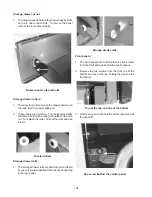
Manifold pipe:
1. Disconnect power, remove the main top, top burners,
control panel and top burner valves.
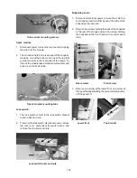
2. Remove the one screw holding the manifold pipe to
the burner box.
Manifold pipe screw
3. Turn the gas off to the range, disconnect the gas
tube that goes from the manifold to the oven valve
using a 9/16” wrench and lift the manifold pipe out.
Manifold tubing connection
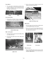
Door latch handle knob:
1. The latch handle knob is held in place by one phillip
head screws. Remove the screw and slide knob off.
Latch handle screw
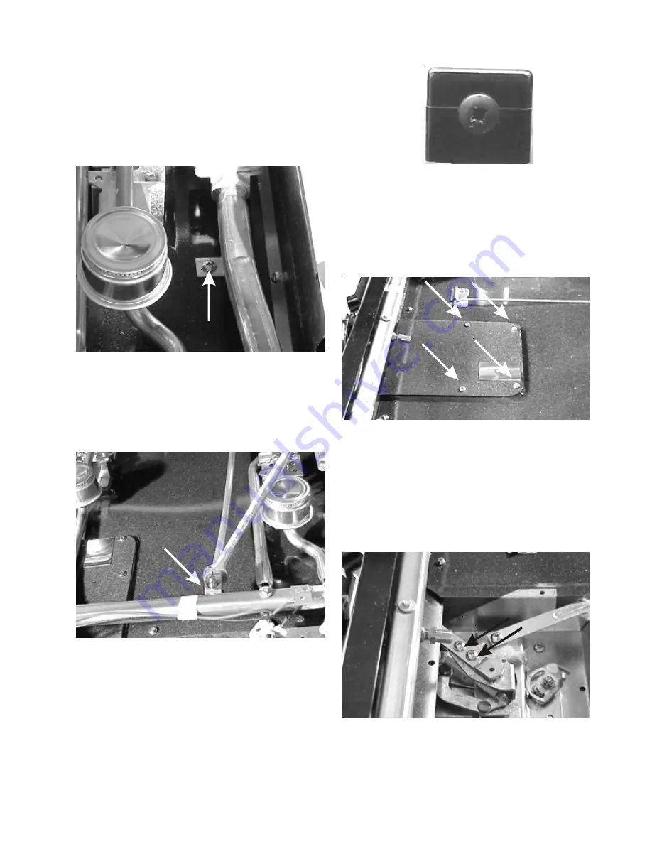
Lock mechanism cover:
1. To remove the lock mechanism cover, remove the
four screws holding the cover to the burner box and
lift the cover off.
Lock mechanism cover
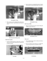
Lock mechanism arm:
1. To remove the lock mechanism remove the lock
mechanism cover, remove the two screws holding
the holding the arm to the lock mechanism and pull
the arm out the front of the range.
Lock arm screws
Summary of Contents for 30" GAS FREESTANDING RANGES
Page 43: ...43 SAMPLE SCHEMATIC FOR ES100 CONTROL SYSTEM ...
Page 50: ...50 SAMPLE SCHEMATIC FOR ES 200 CONTROL SYSTEM ...
Page 60: ...60 SAMPLE SCHEMATIC FOR ES 300 CONTROL SYSTEM ...
Page 72: ...72 SAMPLE SCHEMATIC FOR ES 400 CONTROL SYSTEM ...
Page 84: ...84 SAMPLE SCHEMATIC FOR ES 450 CONTROL SYSTEM ...
Page 93: ...93 Sample schematic for 36 gas range ...
Page 130: ...130 NOTES ...
Page 131: ...131 NOTES ...
Page 132: ...132 ...


