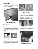
109
4. Drop the assembly down and tip the rear of the
assembly up to disengage the lock rod.
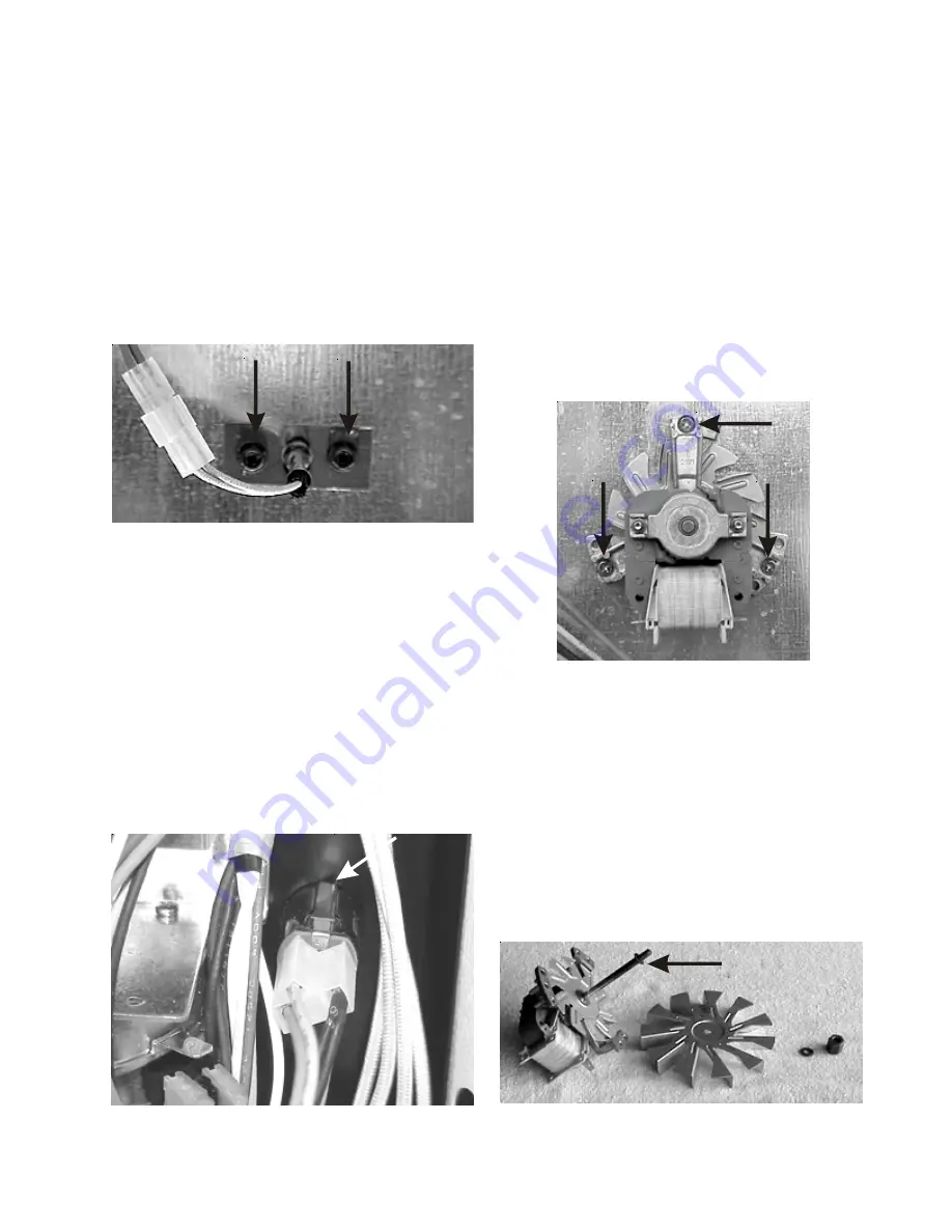
Removing oven sensor:
1. Disconnect electrical power from the range.
2. Unplug the oven sensor.
3. Remove the two screws holding the sensor to the
back of the range.
Oven sensor screws
Door switch and rod removal:
1. Disconnect power from range.
2. Remove main top, burner pan and back cover.
3. Squeeze the spring loaded tabs of the door switch
and push into range. Once the switch clears the
back panel, the switch can be unhooked from the
rod and the rod slid back into the range.
Door switch tabs
Removing convection and speed bake motor
assemblies:
1
Disconnect electrical power and remove back
panel.
2. Remove fan blade inside oven. (See fan blade
removal.)
3. Mark and remove the wires from motor assembly.
4. Remove the three screws holding the assembly to
the back of the range.
Fan motor screws
5. Pull the motor shaft out the back of the range.
6. The fan blade is spaced on the shaft by a C clip and
the cooling fan blade is held in place on the shaft by
a tennamen nut.
C clip
Summary of Contents for 30" GAS FREESTANDING RANGES
Page 43: ...43 SAMPLE SCHEMATIC FOR ES100 CONTROL SYSTEM ...
Page 50: ...50 SAMPLE SCHEMATIC FOR ES 200 CONTROL SYSTEM ...
Page 60: ...60 SAMPLE SCHEMATIC FOR ES 300 CONTROL SYSTEM ...
Page 72: ...72 SAMPLE SCHEMATIC FOR ES 400 CONTROL SYSTEM ...
Page 84: ...84 SAMPLE SCHEMATIC FOR ES 450 CONTROL SYSTEM ...
Page 93: ...93 Sample schematic for 36 gas range ...
Page 130: ...130 NOTES ...
Page 131: ...131 NOTES ...
Page 132: ...132 ...


