


96
SECTION D - DISASSEMBLY AND PARTS
REPLACEMENT
30”RANGE
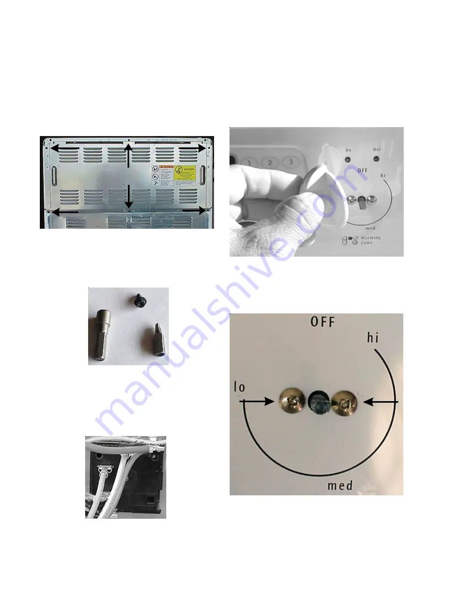
Backguard back panel:
1. Disconnect power from range.
2. Remove six screws and lift the panel off.
Backguard back panel
Note:
Screws may be removed using either a 1/4” nut
driver or an S1 square drive.
Infinite Switches used for surface elements, warm
and serve zone, and warming drawer (if equipped:
1. Disconnect power from the range.
2. Remove the back panel from the backguard.
3. Mark and disconnect the wires from the infinite
switch.
4. Remove the knob by pulling straight off.
Knob
5. Remove the two phillips-head screws holding the
switch to the control panel.
Two Screws
6. Pull the switch from the back of the range.
Infinite switch
1/4”
S1
Summary of Contents for 30" GAS FREESTANDING RANGES
Page 43: ...43 SAMPLE SCHEMATIC FOR ES100 CONTROL SYSTEM ...
Page 50: ...50 SAMPLE SCHEMATIC FOR ES 200 CONTROL SYSTEM ...
Page 60: ...60 SAMPLE SCHEMATIC FOR ES 300 CONTROL SYSTEM ...
Page 72: ...72 SAMPLE SCHEMATIC FOR ES 400 CONTROL SYSTEM ...
Page 84: ...84 SAMPLE SCHEMATIC FOR ES 450 CONTROL SYSTEM ...
Page 93: ...93 Sample schematic for 36 gas range ...
Page 130: ...130 NOTES ...
Page 131: ...131 NOTES ...
Page 132: ...132 ...


