


107
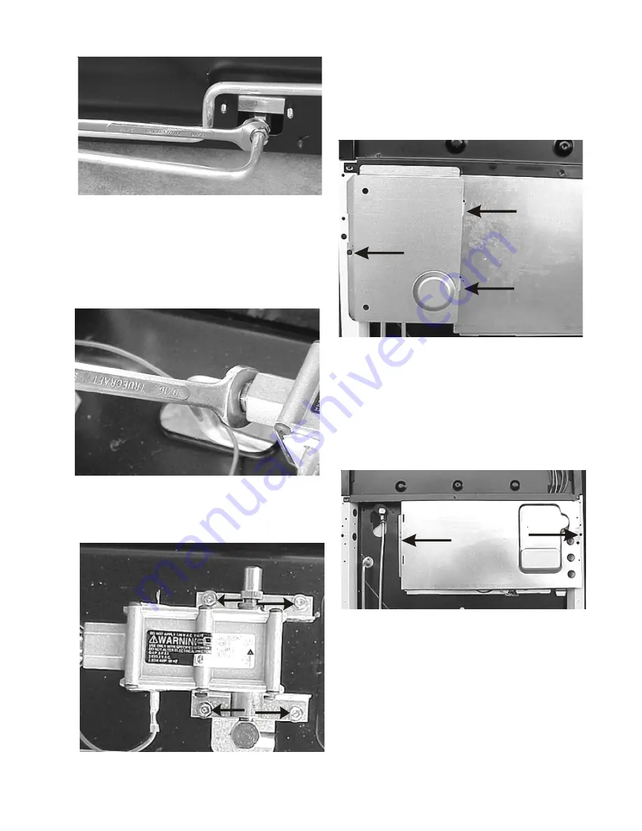
Disconnecting tubing at rear of safety valve
3. Remove storage drawer and disconnect the wires
from the safety valve.
4. Using a 9/16” wrench disconnect the gas tubing at
the valve from the pressure regulator.
Disconnecting tubing inside at safety valve
5. Remove the four screws holding the safety
valve to the rear liner.
Four screws
Removing rear manifold cover:
1. Remove one screw holding the cover to the bodyside
and swing the cover out.
One screw and two tabs
Removing back cover:
1. Disconnect electrical power from the range.
2. Remove rear manifold cover.
3. Remove one screw from each end of the panel.
Back cover screws
Removing the heat shield:
1. Disconnect electrical power from the range and
remove rear cover.
2. Disconnect the wires from the oven light and oven
sensor.
3. Remove the three screws holding the heat shield to
the oven back.
Summary of Contents for 30" GAS FREESTANDING RANGES
Page 43: ...43 SAMPLE SCHEMATIC FOR ES100 CONTROL SYSTEM ...
Page 50: ...50 SAMPLE SCHEMATIC FOR ES 200 CONTROL SYSTEM ...
Page 60: ...60 SAMPLE SCHEMATIC FOR ES 300 CONTROL SYSTEM ...
Page 72: ...72 SAMPLE SCHEMATIC FOR ES 400 CONTROL SYSTEM ...
Page 84: ...84 SAMPLE SCHEMATIC FOR ES 450 CONTROL SYSTEM ...
Page 93: ...93 Sample schematic for 36 gas range ...
Page 130: ...130 NOTES ...
Page 131: ...131 NOTES ...
Page 132: ...132 ...


