Page 5-41
IL17569
Effective June, 2001
Example of Waveform Capture with trigger options
Example 1:
Set Trip2 in Out Relay Config. to any protection
function. Set Trip2 under OSC Trigger in
Waveform Capture to Overwrite. Any Trip2
event will trigger an oscillographic data capture
and write the buffer with new data. This
buffer can however be overwritten.
Example 2:
Set Cntrl PB under OSC Trigger in Waveform
Capture to Locked. Trigger oscillographic data
capture by entering Trig Waveform Capture
under Control in Status/Control from the front
panel. The data will be captured in a buffer and
then the buffer will be locked. This buffer
cannot be overwritten.
5.5.5 Contact Input Configuration Settings
(Contact input CFG)
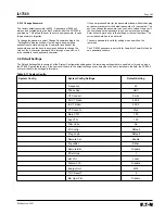
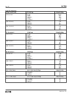
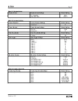
These settings are directly linked to the I/O Configuration setting.
The I/O Config setting in the System Config settings menu must be
set to “custom” for the Contact input CFG settings to be configured
by the user, otherwise the Contact input CFG settings are set to the
default settings as shown in Section 5.6.
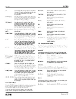
There are eight contact inputs (Cin1 to Cin8) that can be configured
as inputs to pre-defined FP-5000 functions or for user-defined
custom logic. The contact inputs are either on (external contact
closed) or off (external contact open).
User Defined:
This setting is user defined.
52a:
Breaker contact 52a (Open/Trip)
circuit breaker feedback.
52b:
Breaker contact 52b (Close) circuit
breaker feedback.
BFI:
External Breaker Failure Initiation.
Bkr Trouble:
Breaker Trouble
Remote Open:
Remote Breaker Open
Remote Closed:
Remote Breaker Closed
Remote Reset:
Allows remote reset of the Trip and Alarm
Relays and Indicators.
Datalog Trigger:
Allows the datalogger to be triggered from
external contact.
Demand Sync:
Synchronize the Power and Current
demand window.
5.5.6 Output Configuration Settings
These settings are directly linked to the I/O Configuration setting.
The I/O Config setting in the System Config settings menu must be
set to “custom” for the Output Config settings to be configured by
the user, otherwise the Output Config settings are set to the default
settings as shown in Section 5.6.
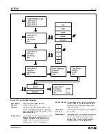
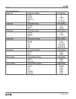
The output configuration settings consist of settings for five Form A
output relays (Output Trip1, Output Trip2, Output Rly3, Output Rly4,
Output Rly5), one Form C Output Alarm relay, the Auxiliary LED,
and three indicators (Trip, Alarm, and Pickup). Output relays Trip1,
Trip2, Rly3, Rly4, and Rly5 are rated for tripping per ANSI C37.90.
The seven output logic gates control the seven outputs, listed
above. Refer to Section 9.2 for more information about the output
logic gates.
There is also another Form C Rly Healthy output relay, which is
non-configurable. When the FP-5000 is energized, the Rly Healthy
energizes after its self-test. This is to provide a fail-safe output
contact meaning that the FP-5000 relay is functioning properly and
is able to protect.
Each programmable output should be configured by the user for the
desired application of the FP-5000. All of the settings to configure
the outputs of the FP-5000 are shown below.
Output Trip1
This Form A relay output is intended to be the main trip relay to
energize the “Breaker Trip” coil. The Trip1 relay is set per the
settings described below.
Monitor:
Set to On or Off. If set to “on”, the “Breaker
Trip” coil circuit will be monitored by the FP-
5000 for continuity through Output Trip1 relay.
See Section 8.9 Breaker-Oriented Functions
for more detailed information.
Function:
Set to OR, AND, NOR, NAND, Disable. The
Function setting defines the configuration of
the output logic gate (with inputs IN1, IN2, IN3,
and IN4) that energizes the Output Trip1 relay.
The default setting is OR. See Section 9 for a
description of the logic input settings.
Dropout:
Set to Latched, Unlatched, or Off Delay. This
setting refers to when Output Trip1 relay is
de-energized after a trip event has occurred.
The default setting is Off Delay.
Latched setting means that the Output Trip1
relay will stay latched until a “Reset” is
initiated either manually, or remotely.
Unlatched setting means that the state of
the Output Trip1 relay directly follows the
state of the associated Output Logic gate.
Example: If the FP-5000 trips on time
overcurrent, then the Output Trip1 relay will
stay energized until the sensed overcurrent
drops below the hysteresis of the current
pickup setting.
Off Delay means that the user can set a
delay time during which the Output Trip1
relay would remain energized after a trip
event has cleared. See Off Delay
setting below.
Off Delay:
Defines the time delay in cycles, which can be
set from 0 to 60 cycles in 1 cycle increments.
Default is set to 5 cycles.
Note: The user should consider the
“breaker clearing time” when setting
the Off Delay.
IN1, IN2, IN3, IN4:
These settings define the logic inputs to the
Output Logic gate associated with Output
Trip1 relay. See Section 9.6 for a description of
the logic input settings.
Output Trip2:
The settings for this Form A relay output are
set the same way as the Output Trip1 relay
settings shown above. The only difference is
the Monitor. If Monitor is set to “on”, the “Breaker
Close” coil circuit will be monitored by the FP-
5000 for continuity through Output Trip2 relay.
Summary of Contents for Cutler-Hammer FP-5000
Page 1: ...IL17569 Effective June 2001 Instructions for FP 5000 Protective Relay...
Page 7: ...IL17569 Table of Contents 6 Effective June 2001 This page left blank intentionally...
Page 13: ...IL17569 Page 2 2 Effective June 2001 Figure 2 2 FP 5000 Simple Wye Connected Application...
Page 14: ...Page 2 3 IL17569 Effective June 2001 Figure 2 3 FP 5000 Simple Open Delta Application...
Page 19: ...IL17569 Page 2 8 Effective June 2001 This page left blank intentionally...
Page 25: ...IL17569 Page 3 6 Effective June 2001 This page left blank intentionally...
Page 98: ...IL17569 Page 5 50 Effective June 2001 This page left blank intentionally...
Page 108: ...IL17569 Page 6 10 Effective June 2001 Figure 6 10 Common Ct Wiring Configurations...
Page 141: ...IL17569 Page 11 4 Effective June 2001 This page left blank intentionally...
Page 165: ...IL17569 Page Appendix 6 Effective June 2001 Figure 13 2 ANSI Very Inverse...
Page 166: ...Page Appendix 7 IL17569 Effective June 2001 Figure 13 3 ANSI Extremely Inverse...
Page 167: ...IL17569 Page Appendix 8 Effective June 2001 Figure 13 4 IEC A Figure 13 4 IEC A...
Page 168: ...Page Appendix 9 IL17569 Effective June 2001 Figure 13 5 IEC B...
Page 169: ...IL17569 Page Appendix 10 Effective June 2001 Figure 13 6 IEC C...
Page 170: ...Page Appendix 11 IL17569 Effective June 2001 Figure 13 7 IEC...
Page 171: ...IL17569 Page Appendix 12 Effective June 2001 Figure 13 8 ANSI...
Page 172: ...Page Appendix 13 IL17569 Effective June 2001 Figure 13 9 Thermal...
Page 173: ...IL17569 Page Appendix 14 Effective June 2001 Figure 13 10 Phase I4 t...
Page 174: ...Page Appendix 15 IL17569 Effective June 2001 Figure 13 11 Phase I2 t...
Page 175: ...IL17569 Page Appendix 16 Effective June 2001 Figure 13 12 Phase It...
Page 176: ...Page Appendix 17 IL17569 Effective June 2001 Figure 13 13 Phase 12 I4 t...
Page 177: ...IL17569 Page Appendix 18 Effective June 2001 Figure 13 14 Phase I2 t...
Page 178: ...Page Appendix 19 IL17569 Effective June 2001 Figure 13 15 Ground IT...
Page 180: ...Page Appendix 21 IL17569 Effective June 2001 This page left blank intentionally...
Page 187: ...Publication No IL17569 June 2001 Pittsburgh Pennsylvania U S A...


