Page 5-35
IL17569
Effective June, 2001
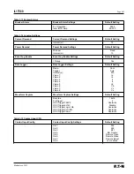
51P PH TOC Setting
This includes the 51 device Phase Inverse Time Overcurrent pickup
and time multiplier settings. A proper coordination study should be
completed to determine the overcurrent pickup and time delay
settings prior to commissioning the FP-5000 relay. The pickup
setting (range: 0.1 to 4.0 per unit in 0.01 steps) is the overcurrent
value in per unit at which the FP-5000 starts to time out to trip. To
reference this setting to the Primary System Current simply multiply
this setting by the Ct primary connected rating. For example, if the
Ct is an 800/5 multi ratio Ct connected at 600/5, then a setting of
0.7 will represent a primary current pickup of 420A (0.7 times 600).
In terms of the relay current used for bench testing, use the nominal
current rating of the FP-5000 model, which is either 5A or 1A. So for
a 5A version a setting of 0.7 will require 3.5A (0.7 times 5) relay
current to operate.
To determine the pickup setting from the coordination study, simply
divide the primary current value that you want the relay to trip at by
the primary Ct rating. For example, if you want the relay to operate
at 570A; set it to 0.95 per unit (570A divided by 600A).
The time multiplier setting (range: 0.05 to 10.0) sets the time portion
of the TOC curve. Refer to Section 13 to view the Inverse Time
Overcurrent Curves. The ANSI and IEC curves and multipliers are
per their respective standards and definitions. The current scale
along the x-axis is in terms of multiples of pickup (I/I
pu
).
For the thermal curves, the current scale along the x-axis is in terms
of I
nom
(or Ct). The time multiplier is defined as the relay trip time at
a current value equal to 3 times (I
nom
) for phase and 1 times (I
nom
) for
ground. The relay trip times are dependent on the curve type
selected. See Section 8 for curve equations and application of the
protective curves and time multipliers.
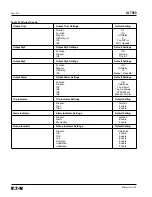
50P-1 PH IOC 1 and 50P-2 PH IOC 2
These are the two 50 device phase instantaneous overcurrent
settings, which are two independent elements. Both units have time
delay settings available. One element could be used for a “Short
Time” element (with a short time delay) and the other as “Instanta-
neous” element (with zero time delay) to improve flexibility and
coordination of the OC curves. The pickup setting (range of 0.1 to
20.0 per unit in 0.01 steps). The time delay may be set from zero to
9999 cycles in 1 cycle steps. The cycle time is based on power
system frequency. The direction setting (fixed at Both) is reserved
for a future version release and operates the same as described
above in the 51P PH TOC Settings.
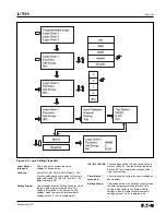
5.5.2.2 IX Measured OC Settings
51X IX TOC Curve
This includes is the 51 device Inverse Time Overcurrent Curve
Setting based on the measured fourth Ct input which is usually used
for neutral or ground overcurrent protection. It is independent from
the phase elements and may have its measurement from a ground
Ct, neutral Ct or residual connection of the phase Cts for ground
current measurement. The user selects the shape and
the reset of the TOC curve. The direction setting is reserved for
a future version and is fixed at Both. The available settings and
setting ranges are the same as the 51P PH TOC settings
described above.
51X IX TOC Setting
This is the 51 device Time Overcurrent pickup and time multiplier
settings based on the measured fourth Ct input. The user selects
the pickup and the time multiplier of the TOC curve. The available
settings and setting ranges are the same as the 51P PH TOC
Settings shown above. The pickup settings are in per unit and are
based on the connected Ct ratio. If a ground Ct is used then the
ratio may be different than the phase Ct ratio. If a residual ground
current connection is used then the Ct ratio is the same as the
phase Ct ratio.
50X-1 IX IOC 1 and 50X-2 IX IOC 2
These are the two 50 device IX instantaneous overcurrent settings,
which are two independent elements. The settings operate the
same as the 50P-1 PH OC 1 and 50P-2 PH OC 2 Settings.
5.5.2.3 IR Residual OC Settings
51R IR TOC Curve
This is the 51 device Residual Inverse Time Overcurrent Curve
Setting, which is a residual ground overcurrent protection function.
This is a calculated ground current from the sum of the measured
phase currents. For a 3-phase, 3-wire system, this current is:
IR = IA + IB + IC. This calculated value is affected by the Ct
Connect Setting in the System Config. settings. In most applications
this function is redundant to the 51X functions described above but
does not require a ground current connection. The user selects the
shape and the reset of the TOC curve. The direction setting is reserved
for a future version and is fixed at Both. The available settings
and setting ranges are the same as the 51P PH TOC settings.
51R IR TOC Setting
This is the 51 device setting Residual Inverse Time Overcurrent
pickup and time multiplier settings. The user selects the pickup and
the time multiplier of the TOC curve. The available settings and
setting ranges are the same as the 51P PH TOC settings. The
pickup settings are in per unit and are based on the connected
phase Ct ratio.
50R-1 IR IOC 1 and 50R-2 IR IOC 2
These are the two 50 device residual IR instantaneous overcurrent
settings, which are two independent elements. The settings operate
the same as described in the 51P PH TOC settings. The pickup settings
are in per unit and are based on the connected phase Ct ratio.
5.5.2.4 Unbalance Settings
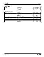
47-1 Voltage Unbal
This is the 47 device Voltage Unbalance setting, which consists of
the Threshold, %(V2/V1), and Delay settings. The voltage unbalance
function is based on the Main VT system 3-phase voltages. The
positive and negative sequence voltages are calculated from the
3-phase voltages.
The Threshold setting defines a minimum operating voltage magnitude
of either V1 or V2 for the 47 function to operate, which ensures that
the relay has a solid basis for initiating a voltage unbalance trip.
This is a supervisory function and not a trip level.
The %(V2/V1) setting is the unbalance trip pickup setting. It is
Summary of Contents for Cutler-Hammer FP-5000
Page 1: ...IL17569 Effective June 2001 Instructions for FP 5000 Protective Relay...
Page 7: ...IL17569 Table of Contents 6 Effective June 2001 This page left blank intentionally...
Page 13: ...IL17569 Page 2 2 Effective June 2001 Figure 2 2 FP 5000 Simple Wye Connected Application...
Page 14: ...Page 2 3 IL17569 Effective June 2001 Figure 2 3 FP 5000 Simple Open Delta Application...
Page 19: ...IL17569 Page 2 8 Effective June 2001 This page left blank intentionally...
Page 25: ...IL17569 Page 3 6 Effective June 2001 This page left blank intentionally...
Page 98: ...IL17569 Page 5 50 Effective June 2001 This page left blank intentionally...
Page 108: ...IL17569 Page 6 10 Effective June 2001 Figure 6 10 Common Ct Wiring Configurations...
Page 141: ...IL17569 Page 11 4 Effective June 2001 This page left blank intentionally...
Page 165: ...IL17569 Page Appendix 6 Effective June 2001 Figure 13 2 ANSI Very Inverse...
Page 166: ...Page Appendix 7 IL17569 Effective June 2001 Figure 13 3 ANSI Extremely Inverse...
Page 167: ...IL17569 Page Appendix 8 Effective June 2001 Figure 13 4 IEC A Figure 13 4 IEC A...
Page 168: ...Page Appendix 9 IL17569 Effective June 2001 Figure 13 5 IEC B...
Page 169: ...IL17569 Page Appendix 10 Effective June 2001 Figure 13 6 IEC C...
Page 170: ...Page Appendix 11 IL17569 Effective June 2001 Figure 13 7 IEC...
Page 171: ...IL17569 Page Appendix 12 Effective June 2001 Figure 13 8 ANSI...
Page 172: ...Page Appendix 13 IL17569 Effective June 2001 Figure 13 9 Thermal...
Page 173: ...IL17569 Page Appendix 14 Effective June 2001 Figure 13 10 Phase I4 t...
Page 174: ...Page Appendix 15 IL17569 Effective June 2001 Figure 13 11 Phase I2 t...
Page 175: ...IL17569 Page Appendix 16 Effective June 2001 Figure 13 12 Phase It...
Page 176: ...Page Appendix 17 IL17569 Effective June 2001 Figure 13 13 Phase 12 I4 t...
Page 177: ...IL17569 Page Appendix 18 Effective June 2001 Figure 13 14 Phase I2 t...
Page 178: ...Page Appendix 19 IL17569 Effective June 2001 Figure 13 15 Ground IT...
Page 180: ...Page Appendix 21 IL17569 Effective June 2001 This page left blank intentionally...
Page 187: ...Publication No IL17569 June 2001 Pittsburgh Pennsylvania U S A...


