IL17569
Page Appendix-2
Effective June, 2001
IP Address
A 32-bit number containing both a subnet address and a host address
that identify a device in a network.
IR
Residual ground current calculated for the three phases, Ia + Ib +Ic, is a calculated value
not measured directly. It will be different on a 4-wire system.
IOC
Instantaneous Over Current protective function; The IOC functions have an optional time
delay for coordination with other relays.
IX
Current measured by a fourth system current transformer. This could be a physical ground
measurement from a residual current connection of the phase Cts.
LAN
Local Area Network.
Left Mouse Button
The primary mouse button, unless you have configured your mouse differently. When
instructed to click on an item, point to it and press the left mouse button.
List Box
A box on a pop-up screen that displays information, allowing you to scroll through
or select its contents.
Modbus protocol
A popular industrial communication protocol.
MODEM
Modulator/Demodulator – encodes and decodes data stream, typically
for transmission over telephone lines.
Mouse
A hand-held pointer that attaches to your computer. The mouse displays on the computer
screen as an arrow. By moving the mouse and clicking the mouse buttons, you can perform
and select various operations.
PC
Personal Computer based upon the Intel™ processor family.
Phase Reversal
When any two phases become reversed.
Phase Unbalance
Deviation of the percentage of nominal line voltage between any two phases.
Point
To position the pointer so that it is resting on the desired item on the screen.
Pointer
The hollow white arrow that you can move around the screen using the mouse.
Pop-Up Screens
A screen that displays access to a PC program function, prompting you to enter
additional information.
Power Flow
Power Flow is the direction of power flow for each harmonic, and is defined as the sign of
WATTS = [Id*Vd + Iq*Vq] for that harmonic. Thus, a positive power flow is power into the load,
and a negative power flow is power being generated by the load. Power should be greater
than 2% of the full load to be sure the result has significance. Zero power should default to
a positive power flow.
Reactive Power (VARs
)
Reactive power or energy associated with the displacement power factor is power factor
correctable (Volt-Amperes Reactive). It is sometimes referred to as the “Q” or “Q-Hours.”
Calculation of the “Q” will use the technique of multiplying voltage samples by the associ-
ated current samples taken 90° earlier. Thus, a leading power factor will follow the conven-
tion of being positive.
Real Power (Watts)
Real power is computed by summing the product of the individual current and voltage
readings over one cycle.
Right Mouse Button
The secondary mouse button, unless you have configured your mouse differently. Use the
right mouse button only when specifically instructed to do so.
rms
The rms value of a quantity X follows the standard definition of: With sufficient sampling,
harmonics will be included in the rms values.
RS-232
A standard that defines the electrical characteristics of a widely-used
serial communication link.
T/H
Track and Hold.
Summary of Contents for Cutler-Hammer FP-5000
Page 1: ...IL17569 Effective June 2001 Instructions for FP 5000 Protective Relay...
Page 7: ...IL17569 Table of Contents 6 Effective June 2001 This page left blank intentionally...
Page 13: ...IL17569 Page 2 2 Effective June 2001 Figure 2 2 FP 5000 Simple Wye Connected Application...
Page 14: ...Page 2 3 IL17569 Effective June 2001 Figure 2 3 FP 5000 Simple Open Delta Application...
Page 19: ...IL17569 Page 2 8 Effective June 2001 This page left blank intentionally...
Page 25: ...IL17569 Page 3 6 Effective June 2001 This page left blank intentionally...
Page 98: ...IL17569 Page 5 50 Effective June 2001 This page left blank intentionally...
Page 108: ...IL17569 Page 6 10 Effective June 2001 Figure 6 10 Common Ct Wiring Configurations...
Page 141: ...IL17569 Page 11 4 Effective June 2001 This page left blank intentionally...
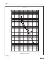
Page 165: ...IL17569 Page Appendix 6 Effective June 2001 Figure 13 2 ANSI Very Inverse...
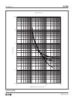
Page 166: ...Page Appendix 7 IL17569 Effective June 2001 Figure 13 3 ANSI Extremely Inverse...
Page 167: ...IL17569 Page Appendix 8 Effective June 2001 Figure 13 4 IEC A Figure 13 4 IEC A...
Page 168: ...Page Appendix 9 IL17569 Effective June 2001 Figure 13 5 IEC B...
Page 169: ...IL17569 Page Appendix 10 Effective June 2001 Figure 13 6 IEC C...
Page 170: ...Page Appendix 11 IL17569 Effective June 2001 Figure 13 7 IEC...
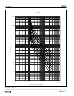
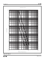
Page 171: ...IL17569 Page Appendix 12 Effective June 2001 Figure 13 8 ANSI...
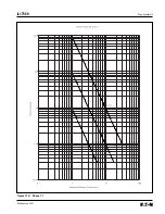
Page 172: ...Page Appendix 13 IL17569 Effective June 2001 Figure 13 9 Thermal...
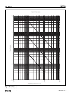
Page 173: ...IL17569 Page Appendix 14 Effective June 2001 Figure 13 10 Phase I4 t...
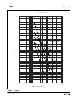
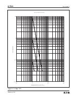
Page 174: ...Page Appendix 15 IL17569 Effective June 2001 Figure 13 11 Phase I2 t...
Page 175: ...IL17569 Page Appendix 16 Effective June 2001 Figure 13 12 Phase It...
Page 176: ...Page Appendix 17 IL17569 Effective June 2001 Figure 13 13 Phase 12 I4 t...
Page 177: ...IL17569 Page Appendix 18 Effective June 2001 Figure 13 14 Phase I2 t...
Page 178: ...Page Appendix 19 IL17569 Effective June 2001 Figure 13 15 Ground IT...
Page 180: ...Page Appendix 21 IL17569 Effective June 2001 This page left blank intentionally...
Page 187: ...Publication No IL17569 June 2001 Pittsburgh Pennsylvania U S A...


