Page 2-7
IL17569
Effective June, 2001
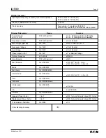
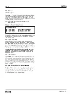
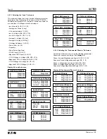
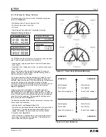
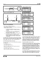
2.5.6 Default Settings
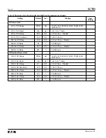
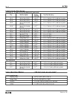
Please refer to the default settings as listed in Table 5.3 FP-5000
Setting Table. The default settings are those loaded into the
program memory at the factory. Restoration to default settings
can only be accomplished by deliberate user actions. No
internal control action can cause the FP-5000 to reset itself to
default settings.
Restoring settings to factory defaults shown in
Section 5.3 once alternative values are programmed involves one of
three actions:
1. Manually input the default values for those changed through the
Settings mode.
2. Completely restore to default settings through the Default
Setting Control under the Status/Control mode function.
3. Execution of external communication commands. The user
may also re-program individual settings or return all settings to
default by INCOM Command(s) through either the rear INCOM
port (J1), or through the front panel RS-232 Serial port. This
functionality is incorporated into the Cutler-Hammer software
that operates through these ports, for instance PowerNet
or
PowerPort.
We will emphasize restoring the defaults through No. 2 above, using
the front panel capabilities of the FP-5000.
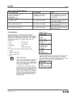
2.5.7 Restoring Default Settings
To assure a known starting point, unless you know that the
FP-5000 is pre-programmed to the required settings, return
the FP-5000 to its default programmed settings.
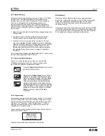
Press the
Status/Control
pushbutton to access
the Default Setting Control.
After pressing
Status/Control
, select “Default
Setting Ctr,” and press the
Enter
pushbutton.
Select “Load Default Setting” and press
Enter
again. The Password Window will appear to
verify your authorization to make the desired
change in settings back to the default values.
After password entry, select “Load ALL Settings”
and press
Enter
. A final verification display will
enable you to accept the change by pressing
Enter
or cancel by using the
Previous
pushbutton.
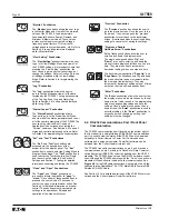
2.5.8 Programming
Programming consists of selecting “System Config” or “Protection”
from the “Setting Main” list. For the “System Config” items, simply
scroll to the item, select with Enter, vary with Up/Down, and select
with Enter. For “Protection,” select “Setting Group 1” (the only
default group enabled) and scroll to select the functions to be
changed as for “System Config.”
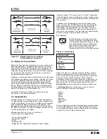
To save settings, press Previous until the screen requires Enter to
Save or Previous to Cancel.
Press the key desired and this operation is completed.
Update Settings?
ENTER to Save
Previous to Cancel
Reset to Exit Set
2.6 Startup
Startup consists of programming the necessary operational
parameters, verifying the operation of the FP-5000, checking the
wiring, and verifying the reasonable operation of the system
components before attempting to place the equipment into
continuous service.
The programming should already be done by the time the FP-5000
is wired into a system and about to be Started Up and placed into
service. Follow Section 7 for start procedures and refer to Section
6.3 for guidance in making connections during startup.
Summary of Contents for Cutler-Hammer FP-5000
Page 1: ...IL17569 Effective June 2001 Instructions for FP 5000 Protective Relay...
Page 7: ...IL17569 Table of Contents 6 Effective June 2001 This page left blank intentionally...
Page 13: ...IL17569 Page 2 2 Effective June 2001 Figure 2 2 FP 5000 Simple Wye Connected Application...
Page 14: ...Page 2 3 IL17569 Effective June 2001 Figure 2 3 FP 5000 Simple Open Delta Application...
Page 19: ...IL17569 Page 2 8 Effective June 2001 This page left blank intentionally...
Page 25: ...IL17569 Page 3 6 Effective June 2001 This page left blank intentionally...
Page 98: ...IL17569 Page 5 50 Effective June 2001 This page left blank intentionally...
Page 108: ...IL17569 Page 6 10 Effective June 2001 Figure 6 10 Common Ct Wiring Configurations...
Page 141: ...IL17569 Page 11 4 Effective June 2001 This page left blank intentionally...
Page 165: ...IL17569 Page Appendix 6 Effective June 2001 Figure 13 2 ANSI Very Inverse...
Page 166: ...Page Appendix 7 IL17569 Effective June 2001 Figure 13 3 ANSI Extremely Inverse...
Page 167: ...IL17569 Page Appendix 8 Effective June 2001 Figure 13 4 IEC A Figure 13 4 IEC A...
Page 168: ...Page Appendix 9 IL17569 Effective June 2001 Figure 13 5 IEC B...
Page 169: ...IL17569 Page Appendix 10 Effective June 2001 Figure 13 6 IEC C...
Page 170: ...Page Appendix 11 IL17569 Effective June 2001 Figure 13 7 IEC...
Page 171: ...IL17569 Page Appendix 12 Effective June 2001 Figure 13 8 ANSI...
Page 172: ...Page Appendix 13 IL17569 Effective June 2001 Figure 13 9 Thermal...
Page 173: ...IL17569 Page Appendix 14 Effective June 2001 Figure 13 10 Phase I4 t...
Page 174: ...Page Appendix 15 IL17569 Effective June 2001 Figure 13 11 Phase I2 t...
Page 175: ...IL17569 Page Appendix 16 Effective June 2001 Figure 13 12 Phase It...
Page 176: ...Page Appendix 17 IL17569 Effective June 2001 Figure 13 13 Phase 12 I4 t...
Page 177: ...IL17569 Page Appendix 18 Effective June 2001 Figure 13 14 Phase I2 t...
Page 178: ...Page Appendix 19 IL17569 Effective June 2001 Figure 13 15 Ground IT...
Page 180: ...Page Appendix 21 IL17569 Effective June 2001 This page left blank intentionally...
Page 187: ...Publication No IL17569 June 2001 Pittsburgh Pennsylvania U S A...


