Page 6-3
IL17569
Effective June, 2001
wit
h 5
A c
t m
od
ule
Ins
tru
ctio
n L
eaf
let
Cau
tio
n -
Re
fer
to
DC
48
-12
5 V
dc
AC
10
0-1
20 V
ac,
50
/60
H
z
Po
we
r S
up
ply
Inp
ut.
FP5
000
Pro
tec
tiv
e R
elay
Ter
m.
1, 2
.
6.3 Wiring – General
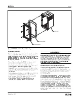
The main electrical interconnections are made from the rear of the
outer case of the FP-5000. The mounting and wiring can be done
with the inner chassis withdrawn from the outer case. Terminal lugs
should be used to wire to the FP-5000. The terminal lugs are
inserted by loosening the screws of the terminal blocks mounted on
the rear of the outer case.
When routing wires between the FP-5000 and the associated
machine or process equipment, follow these guidelines:
• Do not route the control wiring through the high voltage compart-
ment of the gear in which the FP-5000 is mounted.
• Separate the lower voltage connections from the higher voltage
(440V AC or higher) conductors as much as possible. In general,
maintain a minimum distance of 1.5 feet (45 cm) between
the two types.
• Any low voltage control wiring routed out of the cabinet should be
at least #18 AWG stranded copper wire, AWG maximum.
• Any Ct wiring routed out of the cabinet should be at least #14
AWG stranded copper wire, 10 AWG maximum.
• Communications circuits may use thinner conductors, as
recommended in installation literature for those circuits.
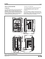
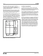
Figure 6-3. FP-5000 IQ Cutout Retrofit Mounting
WARNING
BEFORE WORKING WITH THE WIRING, MAKE SURE POWER
IS DISCONNECTED FROM THE FP-5000, AND ALL REMOTE
CONNECTIONS INCLUDING CONTACT OUTPUT CONTROL
CIRCUITS AND REMOTE INPUT CONTACTS. OTHERWISE,
HAZARDOUS VOLTAGES COULD CAUSE INJURY OR DEATH.
ALSO, UNEXPECTED CONTROL ACTION COULD INJURE
PERSONNEL OR DESTROY EQUIPMENT.
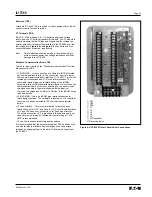
Figure 6-5
shows FP-5000 rear terminal connections.
Connect ground terminal shown in lower left-hand corner of rear
panel (see
Figure 6.4
) to the closest solid electrical-safety
grounding point with a heavy wire or braid (#14 AWG or larger). Do
not use a current-carrying or neutral conductor for this grounding.
6.3.1 Ct Wiring TB4
Carefully read the advice in Section 6.6.2 on choice of Ct ratios for
a given particular application. An inappropriate Ct ratio will result in
poor measurement accuracy and limited protection. More serious
errors in ratio choice will make it impossible to set the relay properly.
Connect the phase and optional ground Cts as shown in
Figure 6-8
.
Pay attention to the phase identification and sequence, and check
for consistent polarity among the three phases. The FP-5000
unbalance protection will pick up and operate if two phases are
swapped, or if the polarity of any Ct is reversed with respect to the
other two. See
Figure 6-10
for other common wiring configurations
such as 3-phase 3-wire, 3-phase 4-wire, 3-phase 3-wire with ground
fault protection.
Summary of Contents for Cutler-Hammer FP-5000
Page 1: ...IL17569 Effective June 2001 Instructions for FP 5000 Protective Relay...
Page 7: ...IL17569 Table of Contents 6 Effective June 2001 This page left blank intentionally...
Page 13: ...IL17569 Page 2 2 Effective June 2001 Figure 2 2 FP 5000 Simple Wye Connected Application...
Page 14: ...Page 2 3 IL17569 Effective June 2001 Figure 2 3 FP 5000 Simple Open Delta Application...
Page 19: ...IL17569 Page 2 8 Effective June 2001 This page left blank intentionally...
Page 25: ...IL17569 Page 3 6 Effective June 2001 This page left blank intentionally...
Page 98: ...IL17569 Page 5 50 Effective June 2001 This page left blank intentionally...
Page 108: ...IL17569 Page 6 10 Effective June 2001 Figure 6 10 Common Ct Wiring Configurations...
Page 141: ...IL17569 Page 11 4 Effective June 2001 This page left blank intentionally...
Page 165: ...IL17569 Page Appendix 6 Effective June 2001 Figure 13 2 ANSI Very Inverse...
Page 166: ...Page Appendix 7 IL17569 Effective June 2001 Figure 13 3 ANSI Extremely Inverse...
Page 167: ...IL17569 Page Appendix 8 Effective June 2001 Figure 13 4 IEC A Figure 13 4 IEC A...
Page 168: ...Page Appendix 9 IL17569 Effective June 2001 Figure 13 5 IEC B...
Page 169: ...IL17569 Page Appendix 10 Effective June 2001 Figure 13 6 IEC C...
Page 170: ...Page Appendix 11 IL17569 Effective June 2001 Figure 13 7 IEC...
Page 171: ...IL17569 Page Appendix 12 Effective June 2001 Figure 13 8 ANSI...
Page 172: ...Page Appendix 13 IL17569 Effective June 2001 Figure 13 9 Thermal...
Page 173: ...IL17569 Page Appendix 14 Effective June 2001 Figure 13 10 Phase I4 t...
Page 174: ...Page Appendix 15 IL17569 Effective June 2001 Figure 13 11 Phase I2 t...
Page 175: ...IL17569 Page Appendix 16 Effective June 2001 Figure 13 12 Phase It...
Page 176: ...Page Appendix 17 IL17569 Effective June 2001 Figure 13 13 Phase 12 I4 t...
Page 177: ...IL17569 Page Appendix 18 Effective June 2001 Figure 13 14 Phase I2 t...
Page 178: ...Page Appendix 19 IL17569 Effective June 2001 Figure 13 15 Ground IT...
Page 180: ...Page Appendix 21 IL17569 Effective June 2001 This page left blank intentionally...
Page 187: ...Publication No IL17569 June 2001 Pittsburgh Pennsylvania U S A...


