


Page 2-5
IL17569
Effective June, 2001
We will only be concerned with System Config and Protection
settings here.
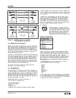
Select the category and press the Enter pushbutton to proceed. The
actual setting of values will be covered in Section 2.5.5.
2.5.4 Minimum Program Requirements
Default settings are provided to minimize the number of manual
programming steps for typical applications. For more complex
applications cases, the use of computer generated setting files
simplifies the setting process. The user programs through the RS-
232 front panel port by use of the PowerPort
TM
Windows
®
based or
PowerNet
TM
Software program. This subject is treated more
extensively later in the manual.
2.5.5 Functions Which Must be Programmed
The FP-5000 comes pre-configured with default or factory settings.
The phase and ground overcurrent functions are the only protection
functions enabled. All other protection functions are turned off and
must be set to enable their operation. The I/O comes pre-configured
as default from the factory for the most common applications. The
I/O can be changed per the requirements of the user’s application.
For now we assume that the default settings will be adequate
except for the following list of functions, which the user must
program in order to handle the specific characteristics of your
system. Since only one protection setting Group is enabled, we
need only program the one group of protection settings and the
values necessary to define the proper operating environment of the
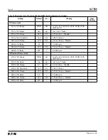
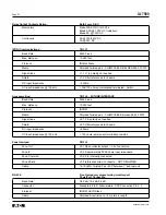
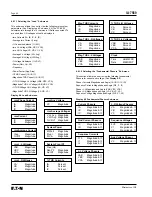
FP-5000. Please refer to Table 2.1 Minimum List of Functions
Which MUST be Programmed for those items.
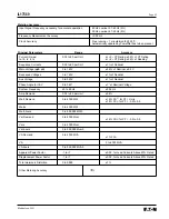
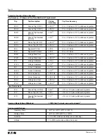
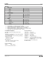
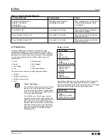
Table 2.1 Minimum List of Functions Which MUST be Programmed
Setting
Default
Incr
Display
User
Setting
System Configuration
Frequency
60
List
50Hz, 60Hz
Phase Sequence, “Phase Seq”
ABC
List
ABC, ACB
Ct Connect
3-Wire
List
3-Wire, 4ct In, 4ct Ig
Phase Ct Primary, “PH CT Pri”
500:Ct
1
Ct-6000:Ct, where Ct is 1 or 5 Amp based
on CT board jumper
Neutral Ct Primary, “NU CT Pri”
500:Ct
1
Ct-6000:Ct, where Ct is 1 or 5 Amp based
on CT board jumper
VT Connect
Wye
List
Wye, Delta
Main VT Ratio, “Main VTR”
100
1
1-8000 Volt
Aux VT Ratio, “Aux VTR”
100
1
1-8000 Volt
TOC Reset Time, “TOC ResetT”
5
1
1-20 cycles
Protection/Group 1
Phase Overcurrent
51P Ph TOC Shape
MOD
List
IT, I2T, I4T, FLAT, MOD, VERY, XTRM, IECA,
IECB, IECC
51P Ph TOC Reset
Calc
List
Inst, Calc, T Delay
51P Ph TOC Pickup
1.00
0.01
0.10-4.00 p.u., “Disable”
51P Ph TOC TIme Multi
1.00
0.01
0.05-10.00 p.u.
50P1 Ph OC Pickup
2.00
0.01
0.10-20.00 p.u., “Disable”
50P1 Ph OC Delay
0
1
0-9999 cycle
50P2 Ph OC Pickup
3.00
0.01
0.10-20.00 p.u., “Disable”
50P2 Ph OC Delay
15
1
0-9999 cycle
Summary of Contents for Cutler-Hammer FP-5000
Page 1: ...IL17569 Effective June 2001 Instructions for FP 5000 Protective Relay...
Page 7: ...IL17569 Table of Contents 6 Effective June 2001 This page left blank intentionally...
Page 13: ...IL17569 Page 2 2 Effective June 2001 Figure 2 2 FP 5000 Simple Wye Connected Application...
Page 14: ...Page 2 3 IL17569 Effective June 2001 Figure 2 3 FP 5000 Simple Open Delta Application...
Page 19: ...IL17569 Page 2 8 Effective June 2001 This page left blank intentionally...
Page 25: ...IL17569 Page 3 6 Effective June 2001 This page left blank intentionally...
Page 98: ...IL17569 Page 5 50 Effective June 2001 This page left blank intentionally...
Page 108: ...IL17569 Page 6 10 Effective June 2001 Figure 6 10 Common Ct Wiring Configurations...
Page 141: ...IL17569 Page 11 4 Effective June 2001 This page left blank intentionally...
Page 165: ...IL17569 Page Appendix 6 Effective June 2001 Figure 13 2 ANSI Very Inverse...
Page 166: ...Page Appendix 7 IL17569 Effective June 2001 Figure 13 3 ANSI Extremely Inverse...
Page 167: ...IL17569 Page Appendix 8 Effective June 2001 Figure 13 4 IEC A Figure 13 4 IEC A...
Page 168: ...Page Appendix 9 IL17569 Effective June 2001 Figure 13 5 IEC B...
Page 169: ...IL17569 Page Appendix 10 Effective June 2001 Figure 13 6 IEC C...
Page 170: ...Page Appendix 11 IL17569 Effective June 2001 Figure 13 7 IEC...
Page 171: ...IL17569 Page Appendix 12 Effective June 2001 Figure 13 8 ANSI...
Page 172: ...Page Appendix 13 IL17569 Effective June 2001 Figure 13 9 Thermal...
Page 173: ...IL17569 Page Appendix 14 Effective June 2001 Figure 13 10 Phase I4 t...
Page 174: ...Page Appendix 15 IL17569 Effective June 2001 Figure 13 11 Phase I2 t...
Page 175: ...IL17569 Page Appendix 16 Effective June 2001 Figure 13 12 Phase It...
Page 176: ...Page Appendix 17 IL17569 Effective June 2001 Figure 13 13 Phase 12 I4 t...
Page 177: ...IL17569 Page Appendix 18 Effective June 2001 Figure 13 14 Phase I2 t...
Page 178: ...Page Appendix 19 IL17569 Effective June 2001 Figure 13 15 Ground IT...
Page 180: ...Page Appendix 21 IL17569 Effective June 2001 This page left blank intentionally...
Page 187: ...Publication No IL17569 June 2001 Pittsburgh Pennsylvania U S A...


