


Page 4-3
IL17569
Effective June, 2001
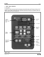
4.3 Pushbuttons
The front operations panel supports 15 membrane switch
pushbuttons. Pressing any of the pushbuttons will initiate many
of the FP-5000 functions and actions. This section gives a complete
description of each pushbutton and its functions. The pushbuttons
can be grouped logically into the 6 display modes, reset and
breaker control.
1. Reset
5. Status/Control
2. Monitor
6. Set (Settings)
3. View Setting
7. Test
4. Log
8. Close Open Breaker
The center section consists of display navigation buttons:
1. Previous
2. Up/Down (single arrow)
3. Up/Down (double arrow)
4. Enter
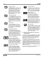
“Reset” Pushbutton:
The “Reset”pushbutton performs many “Reset”
functions, one of which resets the display to
show the default rms current and voltage display
screen from any display menu, when the relay
is in normal monitoring mode.
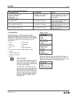
The FP-5000 has a “Reset” menu, which is
accessed by pressing the “Reset” pushbutton
when the unit is in normal monitoring mode. This
menu allows the user to reset all of the relay
functions: trips, alarms, peak current and power
demands, min/max values, history log param-
eters, relays, and the data logger. There is no
password protection for the reset functions.
(See Display 4.2)
Reset Main
Trip
Alarm
Bkr Lockout
Slow Bkr ALM
Relay
Peak Demand Values
Min/Max Values
History Log
Datalog
Energy
Display
Diag Warnings
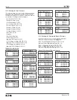
By selecting a Reset sub-menu function listed above by using the
Up/Down arrow and “Enter” pushbutton, the user can reset that
function simply by pushing the “Enter” pushbutton again. The example
below shows the “Trip Flag” sub-menu reset display screen.
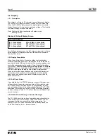
Reset Trip
Press
ENTER To Confirm
PREVIOUS To Cancel
Display 4.2 Reset
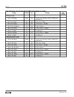
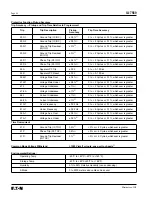
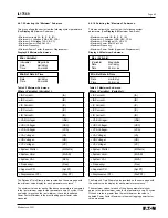
Table 4.1 Transient Display Messages
“Display Message”
Display Mode
Cause
Functions Programmed to
Flashing a few seconds in
When entering PLC, Cin and Cout
default. They can be
the setting-edit mode
in the setting-edit mode if they
viewed only.
are disabled
See System Config.
Fault Test is Off!
5 seconds in Test mode
When stopping fault simulation if
the test was complete
Zone Interlock Output is On
5 seconds in Test mode
When turning the Zone Interlock
output on if it is on
Zone Interlock Output Is Off
5 seconds in Test mode
When turning the Zone Interlock
output off if it is off
Summary of Contents for Cutler-Hammer FP-5000
Page 1: ...IL17569 Effective June 2001 Instructions for FP 5000 Protective Relay...
Page 7: ...IL17569 Table of Contents 6 Effective June 2001 This page left blank intentionally...
Page 13: ...IL17569 Page 2 2 Effective June 2001 Figure 2 2 FP 5000 Simple Wye Connected Application...
Page 14: ...Page 2 3 IL17569 Effective June 2001 Figure 2 3 FP 5000 Simple Open Delta Application...
Page 19: ...IL17569 Page 2 8 Effective June 2001 This page left blank intentionally...
Page 25: ...IL17569 Page 3 6 Effective June 2001 This page left blank intentionally...
Page 98: ...IL17569 Page 5 50 Effective June 2001 This page left blank intentionally...
Page 108: ...IL17569 Page 6 10 Effective June 2001 Figure 6 10 Common Ct Wiring Configurations...
Page 141: ...IL17569 Page 11 4 Effective June 2001 This page left blank intentionally...
Page 165: ...IL17569 Page Appendix 6 Effective June 2001 Figure 13 2 ANSI Very Inverse...
Page 166: ...Page Appendix 7 IL17569 Effective June 2001 Figure 13 3 ANSI Extremely Inverse...
Page 167: ...IL17569 Page Appendix 8 Effective June 2001 Figure 13 4 IEC A Figure 13 4 IEC A...
Page 168: ...Page Appendix 9 IL17569 Effective June 2001 Figure 13 5 IEC B...
Page 169: ...IL17569 Page Appendix 10 Effective June 2001 Figure 13 6 IEC C...
Page 170: ...Page Appendix 11 IL17569 Effective June 2001 Figure 13 7 IEC...
Page 171: ...IL17569 Page Appendix 12 Effective June 2001 Figure 13 8 ANSI...
Page 172: ...Page Appendix 13 IL17569 Effective June 2001 Figure 13 9 Thermal...
Page 173: ...IL17569 Page Appendix 14 Effective June 2001 Figure 13 10 Phase I4 t...
Page 174: ...Page Appendix 15 IL17569 Effective June 2001 Figure 13 11 Phase I2 t...
Page 175: ...IL17569 Page Appendix 16 Effective June 2001 Figure 13 12 Phase It...
Page 176: ...Page Appendix 17 IL17569 Effective June 2001 Figure 13 13 Phase 12 I4 t...
Page 177: ...IL17569 Page Appendix 18 Effective June 2001 Figure 13 14 Phase I2 t...
Page 178: ...Page Appendix 19 IL17569 Effective June 2001 Figure 13 15 Ground IT...
Page 180: ...Page Appendix 21 IL17569 Effective June 2001 This page left blank intentionally...
Page 187: ...Publication No IL17569 June 2001 Pittsburgh Pennsylvania U S A...


