


IL17569
Page 4-2
Effective June, 2001
4.2 Display
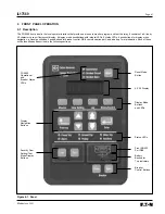
4.2.1 Description
The display is a 4-line by 20-character vacuum fluorescent display.
The first line of all display screens is reserved for the screen title.
When the FP-5000 is first powered, the display lights and should
display the system three-phase currents and voltages. This is called
the default display screen shown below.
Note: Pushing the Reset pushbutton will default to the
following screen.
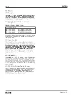
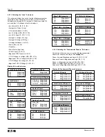
Display 4.1 Default Display Screen
Currents/Voltages
IA = <rms value>
VA or VAB = <rms value>
IB = <rms value>
VB or VBC = <rms value>
IC = <rms value>
VC or VCA = <rms value>
For all other display screens, the first column is reserved for the line
pointer/selector. All display screen data fits within the allocated 3
lines by 20 columns.
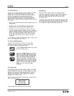
4.2.2 Display Sleep Mode
When the unit sits idle for 15 minutes without any pushbuttons
activated, the display goes into a “Sleep Mode,” in which the screen
goes blank. During this time, the unit is still in normal operating mode
protecting and monitoring the system. Every 5 minutes thereafter,
the message “
FP5000 Feeder Relay Push Any Button To Activate
Display
” appears on the display for 30 seconds. This is a reminder
of how to re-energize the display to the Default Display screen.
When in this mode, the pushbuttons only activate the display, not
the function of the pushbutton. The pushbutton must be pushed
again, once the unit shows the Default Display screen, to do its
pushbutton function.
4.2.3 Self Check Failure
Upon initialization, the FP-5000 performs a series of hardware and
software checks to assure proper operation of the protective relay
unit. These checks cover issues such as programming, memory
and calibration of the unit. If a failure is detected then the FP-5000
operational LED will be out and the FP-5000 will display a warning
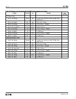
or failure message. Table 12.1 “Self Test Displays and Status Flag”
covers this topic.
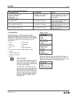
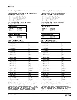
4.2.4 FP-5000 Other Warning or Transient Messages
The FP-5000 has certain modes of operation and actions that may
result in warning or error message. Table 4.2 and Table 12.2 list
messages that may be encountered while programming. For
example if you try to close the breaker that is already closed, the
FP-5000 will display “Error – Breaker Closed.”
Summary of Contents for Cutler-Hammer FP-5000
Page 1: ...IL17569 Effective June 2001 Instructions for FP 5000 Protective Relay...
Page 7: ...IL17569 Table of Contents 6 Effective June 2001 This page left blank intentionally...
Page 13: ...IL17569 Page 2 2 Effective June 2001 Figure 2 2 FP 5000 Simple Wye Connected Application...
Page 14: ...Page 2 3 IL17569 Effective June 2001 Figure 2 3 FP 5000 Simple Open Delta Application...
Page 19: ...IL17569 Page 2 8 Effective June 2001 This page left blank intentionally...
Page 25: ...IL17569 Page 3 6 Effective June 2001 This page left blank intentionally...
Page 98: ...IL17569 Page 5 50 Effective June 2001 This page left blank intentionally...
Page 108: ...IL17569 Page 6 10 Effective June 2001 Figure 6 10 Common Ct Wiring Configurations...
Page 141: ...IL17569 Page 11 4 Effective June 2001 This page left blank intentionally...
Page 165: ...IL17569 Page Appendix 6 Effective June 2001 Figure 13 2 ANSI Very Inverse...
Page 166: ...Page Appendix 7 IL17569 Effective June 2001 Figure 13 3 ANSI Extremely Inverse...
Page 167: ...IL17569 Page Appendix 8 Effective June 2001 Figure 13 4 IEC A Figure 13 4 IEC A...
Page 168: ...Page Appendix 9 IL17569 Effective June 2001 Figure 13 5 IEC B...
Page 169: ...IL17569 Page Appendix 10 Effective June 2001 Figure 13 6 IEC C...
Page 170: ...Page Appendix 11 IL17569 Effective June 2001 Figure 13 7 IEC...
Page 171: ...IL17569 Page Appendix 12 Effective June 2001 Figure 13 8 ANSI...
Page 172: ...Page Appendix 13 IL17569 Effective June 2001 Figure 13 9 Thermal...
Page 173: ...IL17569 Page Appendix 14 Effective June 2001 Figure 13 10 Phase I4 t...
Page 174: ...Page Appendix 15 IL17569 Effective June 2001 Figure 13 11 Phase I2 t...
Page 175: ...IL17569 Page Appendix 16 Effective June 2001 Figure 13 12 Phase It...
Page 176: ...Page Appendix 17 IL17569 Effective June 2001 Figure 13 13 Phase 12 I4 t...
Page 177: ...IL17569 Page Appendix 18 Effective June 2001 Figure 13 14 Phase I2 t...
Page 178: ...Page Appendix 19 IL17569 Effective June 2001 Figure 13 15 Ground IT...
Page 180: ...Page Appendix 21 IL17569 Effective June 2001 This page left blank intentionally...
Page 187: ...Publication No IL17569 June 2001 Pittsburgh Pennsylvania U S A...


